Electrochemical apparatus with reactant micro-channels

a microchannel and reactant technology, applied in the field of fuel cells, can solve the problems of premature combustion and loss of active anode area, failure to control gas flow rate or pressure distribution, damage to the cell, etc., to improve the overall cell reactant balance, enhance the distribution of reactant to the cell, and reduce the complexity of stack components

Inactive Publication Date: 2005-04-12
TECH MANAGEMENT
View PDF38 Cites 32 Cited by
  • Summary
  • Abstract
  • Description
  • Claims
  • Application Information

AI Technical Summary

Benefits of technology

We have found that micro-channels integrated within the electrode structure can be formed in a compact fuel cell. Integrated micro-channels minimize the complexity of stack components. Channels of smaller dimension than those existing in the prior art can be manufactured by a variety of techniques. Using these techniques, flow and pressure distribution can be customized and controlled through the channel design, enhancing reactant distribution to the cell. It has further been found that a fuel cell apparatus employing a network of micro-channels can improve overall cell reactant balance through controlled pressure distribution. It has further been found that employing controlled flow and pressure in a compact integrated device results in an apparatus exhibiting improved volumetric power density and efficiency.
The present invention therefore provides an electrochemical apparatus comprising at least one cell, wherein the cell has a solid electrolyte disposed between an oxygen electrode and a fuel electrode, with at least one separator between adjacent cells contacting the surface of one of the electrodes opposite the electrolyte; wherein at least one electrode of the cell defines a variable cross-section micro-channel pattern, wherein this pattern serves to distribute the flowing gas uniformly within the electrode, regulates the pressure drop of this gas, and also creates preferred local gas velocities, especially where the gas exits the electrode.
The micro-channel is preferably a small size, on the order of about 0.5 millimeter or less, such that the micro-channel can be defined within at least one electrode or separator by low-cost manufacturing techniques.

Problems solved by technology

The increased number of reactions generates an undesirable thermal gradient, which can damage the cell.
These grooves are essentially pathways within the cell, and fail to control gas flow rate or pressure distribution.
In fuel cells which have their anode fuel-exit edges exposed to an oxidizing environment, any anode local exit regions having low fuel mixture velocities may allow oxygen back diffusion into the cell stack, causing premature combustion and loss of active anode area.
The electrochemical processes inherent in the fuel cell's operation become less effective and performance suffers.

Method used


Image

  • Electrochemical apparatus with reactant micro-channels
  • Electrochemical apparatus with reactant micro-channels
  • Electrochemical apparatus with reactant micro-channels

Examples


Embodiment Construction

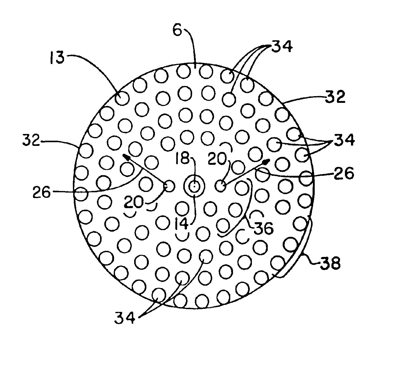
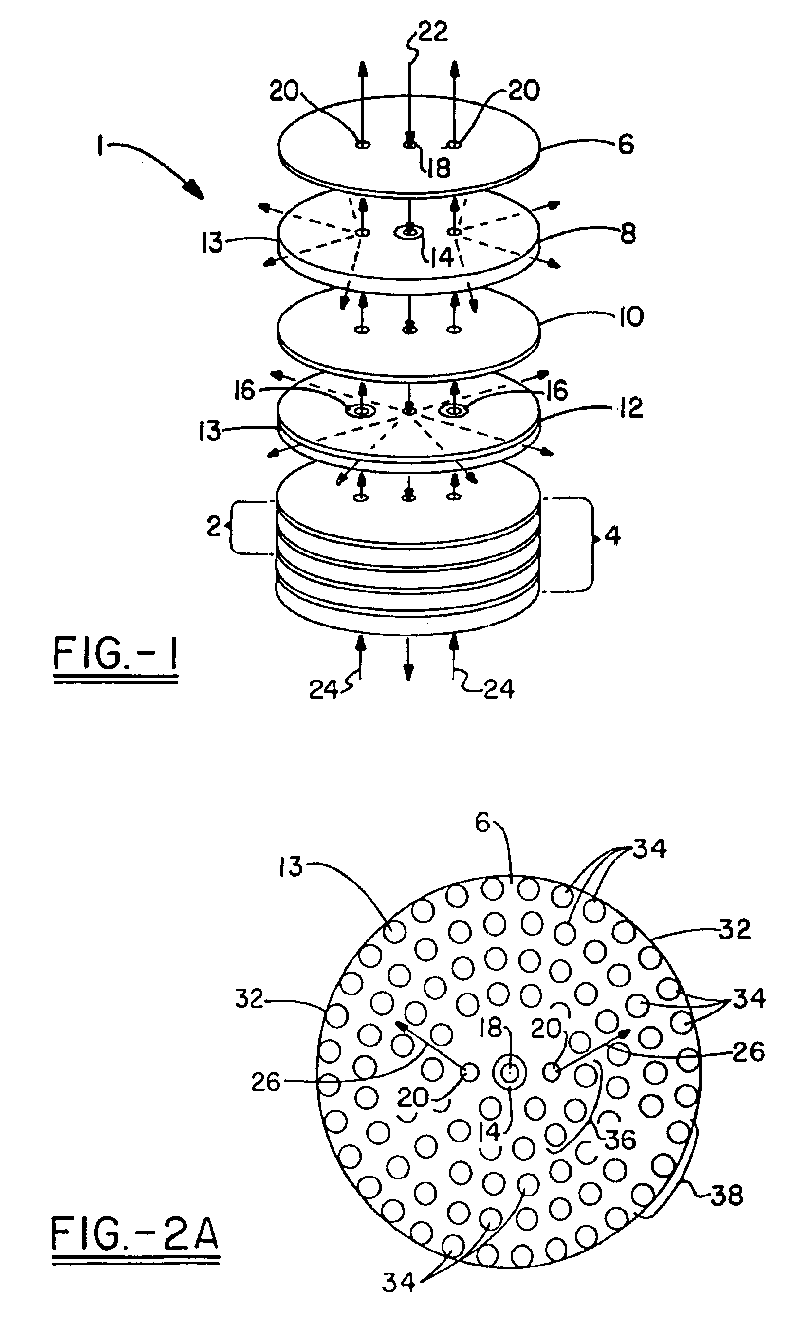
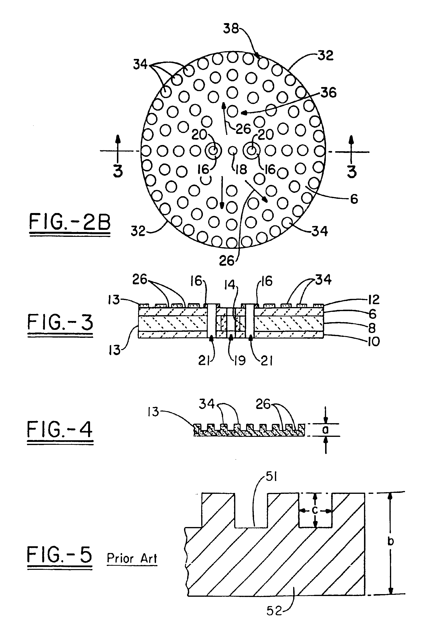
Although applicable to other types of electrochemical apparatus, for purposes of this description the invention will be described in relation to its incorporation into a solid electrolyte (oxide) fuel cell as described in U.S. Pat. No. 5,445,903, incorporated by reference as if reprinted herein. The electrochemical apparatus 1 of one embodiment of the present invention is represented in FIG. 1, which shows a schematic exploded view of one preferred embodiment of a solid-oxide fuel cell 2 and a stack of two such cells 4.

A cell 2 generally comprises four stacked layers: a separator 6, a cathode layer 8, an electrolyte 10, and an anode layer 12. Cathode layer 8 and anode layer 12 may be referred to in the general sense as electrodes 13 and in a preferred embodiment at least one such electrode is comprised of a unitary (single) component as contrasted to an active electrode structure and an associated porous element. A tubular gasket 14 in a cathode layer forms a seal between the nonpor...


PUM

PropertyMeasurementUnit
widthaaaaaaaaaa
sizeaaaaaaaaaa
widthaaaaaaaaaa

Abstract

The present invention is directed generally to an electrochemical apparatus for oxidation or consumption of a fuel, and the generation of electricity, such as, a solid electrolyte fuel cell. The electrochemical apparatus (1) comprises at least one cell (2), wherein the cell (2) has a solid electrolyte (10) disposed between a unitary oxygen electrode (12) and a unitary fuel electrode (8), and at least one separator (6) contacting the surface of one of the electrodes (13) opposite of the electrolyte (10). At least one electrode (13) of the cell (2) defines a micro-channel pattern (26), wherein the micro-channel cross-section is preferably varied, such that reactant gas flowing through the micro channels achieves tailored local flow, pressure, and velocity distributions.

Description

TECHNICAL FIELDThe present invention relates to fuel cells, and more particularly to fuel cells constructed of stacked plate components. More particularly, the present invention relates to fuel cells containing enhanced flow electrodes for fuel and / or air.BACKGROUND OF THE INVENTIONThe invention is directed generally to an electrochemical apparatus for oxidation or consumption of a fuel, and the generation of electricity, such as, a solid electrolyte fuel cell.Although particular embodiments are applicable to conventional co-fired solid electrolyte fuel cell apparatus, the present invention is particularly useful when utilizing non-cofired solid oxide electrolyte fuel cells, preferably planar fuel cells, that contain a stack of multiple assemblies. Each assembly comprises a solid electrolyte disposed between a cathode and an anode, being bounded by separators, which contact the surfaces of the electrodes opposite the electrolyte.The fuel cell operates by conducting ions through the ...

Claims


Application Information

Patent Timeline
Patent Type & Authority Patents(United States)
IPC IPC(8): H01M8/12H01M8/24H01M8/02H01M8/10
CPCH01M8/025H01M8/0258H01M8/026H01M8/2425H01M8/1213H01M8/1004Y02E60/525H01M2300/0074Y02E60/521Y02E60/50H01M8/2483H01M8/2432H01M8/2428H01M8/0265
Inventor RUHL, ROBERT C.MILLIKEN, CHRISTOPHER E.PETRIK, MICHAEL A.
Owner TECH MANAGEMENT
Why Eureka
Try Eureka