
Multi-antenna distribution of wireless broadband in a building

a wireless broadband and multi-antenna technology, applied in diversity/multi-antenna systems, wireless communication, non-interfering antenna combinations, etc., can solve problems such as connectivity and signal strength problems, access problems for cellular telephone users, and difficulty in obtaining a sufficiently strong communication channel between the wap or repeater and various receiving devices, so as to improve the distribution of wireless broadband signal

Active Publication Date: 2015-06-23
CENTURYLINK INTPROP
View PDF8 Cites 136 Cited by
  • Summary
  • Abstract
  • Description
  • Claims
  • Application Information

AI Technical Summary

Benefits of technology

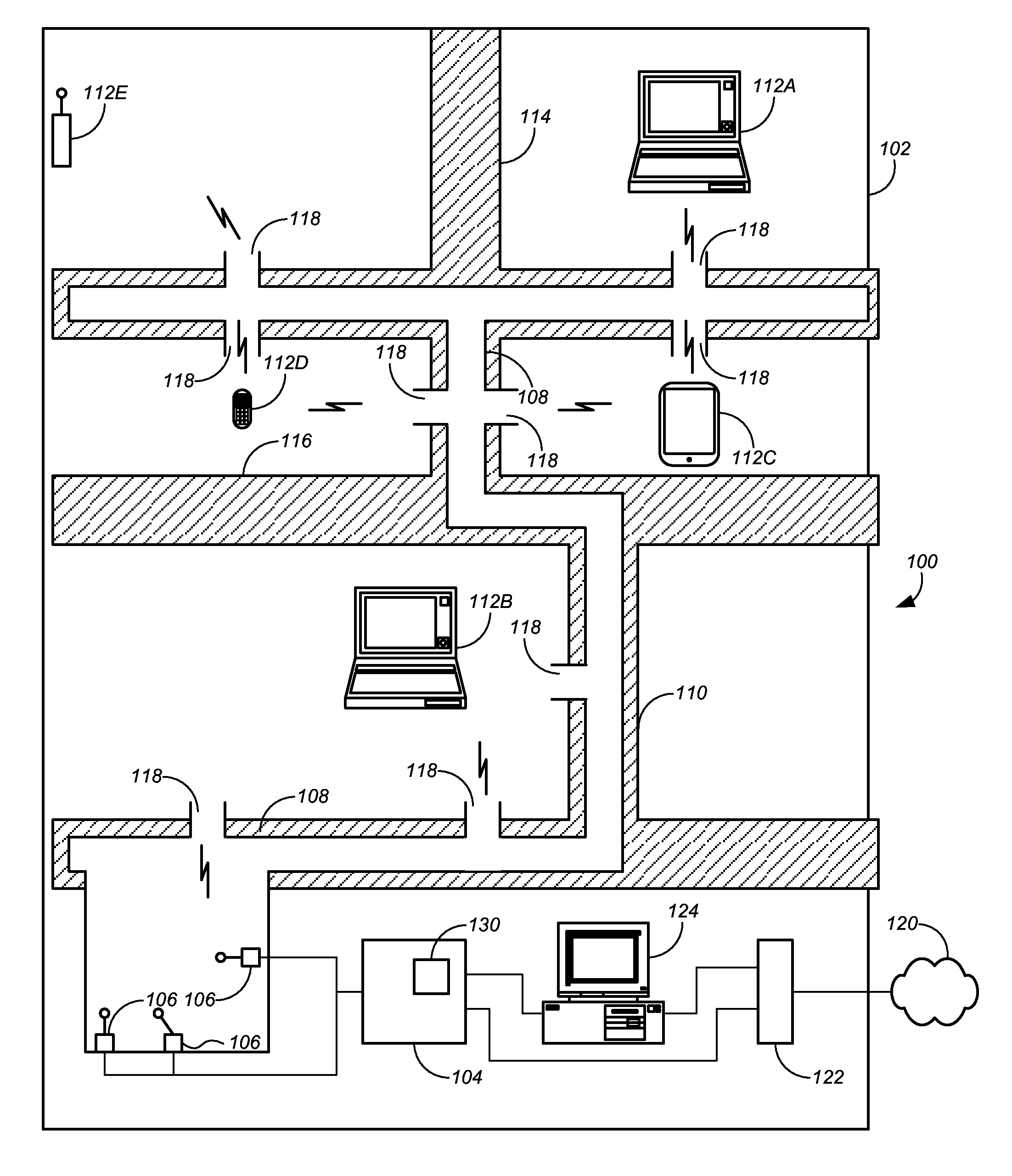
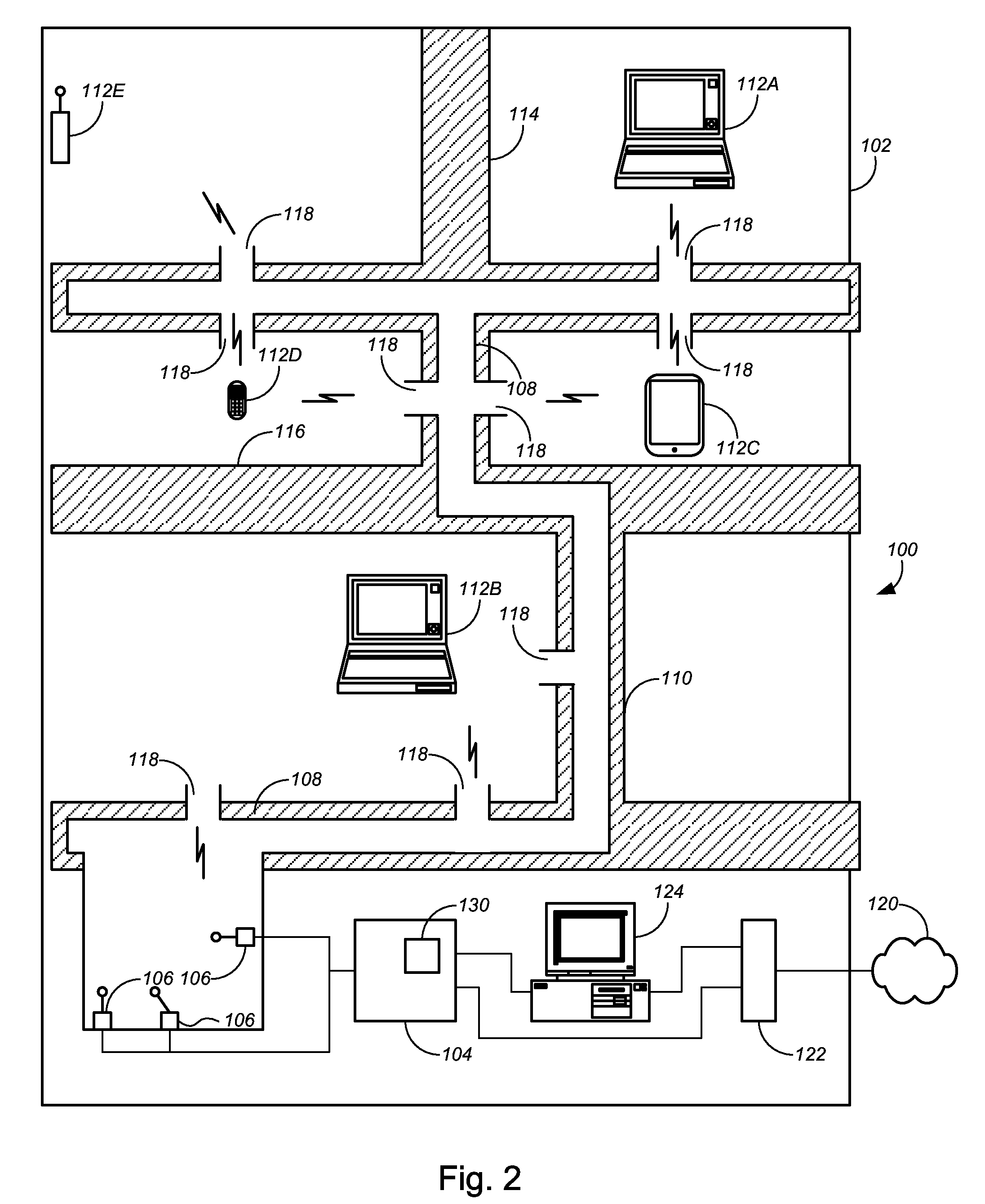
The patent is about methods for distributing wireless signals in buildings using base antennas in the ventilation system. The methods also involve adding receivers to devices already in the building, like cell phones and computers, to optimize communication. By adjusting the configuration of the base antennas, the methods can improve the distribution of the wireless signal and make it easier to access from within the building.

Problems solved by technology

The walls, floors and other structures of the building can attenuate or degrade the original wireless signal sufficiently to cause access problems for cellular telephone users within a building.
One problem with the transmission of wireless broadband signals within a building is difficulty obtaining a sufficiently strong communication channel between the WAP or repeater and various receiving devices.
Connectivity and signal strength problems can be exacerbated by the walls, floors, ceilings and other surfaces or barriers present in a typical building which can cause signal attenuation and reflection.
This solution however involves the cost and inconvenience of duplicate WAPs and additional cabling.
Nonetheless, any wireless system will at some point be limited by the distance between the WAP and wireless devices, which limitations are exacerbated by the walls, floors, ceilings and other surfaces or structures always present in a building.
Bends, kinks, rough surfaces, splits, and variations in duct size or configuration will inevitably cause fading in any RF signal transmitted through a duct waveguide.
The spread spectrum nature of the signal described in the U.S. Pat. No. 6,980,768 provides little opportunity for transmission optimization within a ventilation system.

Method used


Image

  • Multi-antenna distribution of wireless broadband in a building
  • Multi-antenna distribution of wireless broadband in a building
  • Multi-antenna distribution of wireless broadband in a building

Examples


Embodiment Construction

[0026]While various aspects and features of certain embodiments have been summarized above, the following detailed description illustrates a few exemplary embodiments in further detail to enable one of skill in the art to practice such embodiments. The described examples are provided for illustrative purposes and are not intended to limit the scope of the invention.

[0027]In the following description, for the purposes of explanation, numerous specific details are set forth in order to provide a thorough understanding of the described embodiments. It will be apparent to one skilled in the art, however, that other embodiments of the present may be practiced without some of these specific details. In other instances, certain structures and devices are shown in block diagram form. Several embodiments are described herein, and while various features are ascribed to different embodiments, it should be appreciated that the features described with respect to one embodiment may be incorporate...


PUM


Abstract

The disclosed embodiments include methods and systems for distributing a broadband wireless signal in a building. The disclosed methods and systems feature a wireless broadband transmitter associated with multiple base antennas, where the base antennas are inserted into one or more ducts of the ventilation system of the building. Communication between the transmitter and receivers within the building may be optimized by selecting, modifying or controlling a configuration parameter of at least one of the multiple base antennas to enhance distribution of the wireless broadband signal within the ducts of the ventilation system and between the transmitter and device receivers.

Description

COPYRIGHT STATEMENT[0001]A portion of the disclosure of this patent document contains material that is subject to copyright protection. The copyright owner has no objection to the facsimile reproduction by anyone of the patent document or the patent disclosure as it appears in the Patent and Trademark Office patent file or records, but otherwise reserves all copyright rights whatsoever.FIELD[0002]The present disclosure relates, in general, to systems and methods for distributing wireless broadband signals throughout a building and more particularly to the use of optimized multi-antenna distribution methods and systems in conjunction with using the building HVAC ducts as a waveguide system.BACKGROUND[0003]The wireless distribution of broadband signals within a building is becoming commonplace. Wi-Fi is now the most common way people access the Internet. Smart phones compliant with 3G and 4G standards are commonly used inside buildings. Personal computers, laptop computers, cellular p...

Claims


Application Information

Patent Timeline
Patent Type & Authority Patents(United States)
IPC IPC(8): H04H20/71H04W16/00
CPCH04W16/00H01Q3/00H04W16/28H01Q1/007H01Q21/28H04B7/0413H04B7/06H04L12/2801H04W16/20H04W16/26H04W88/04H04W64/003
Inventor SCHWENGLER, THOMAS
Owner CENTURYLINK INTPROP
Learn More