Power converter system and method

a power converter and converter technology, applied in the direction of power conversion systems, ac-ac conversion, circuit arrangements, etc., can solve the problems of reducing the system efficiency, overheating the generator, and using very large and costly filters

Active Publication Date: 2007-05-31
GENERAL ELECTRIC CO
View PDF8 Cites 103 Cited by
  • Summary
  • Abstract
  • Description
  • Claims
  • Application Information

AI Technical Summary

Benefits of technology

[0006] Briefly, according to one embodiment of the invention, an power system for providing an output power to a load is provided. The power system comprises a generator configured to generate an alternating current input power and a power converter system coupled to the generator and configured to generate an output power. The output power is provided to the load through at least one transformer. The power system further comprises a converter control system coupled to the converter system and configured to drive the converter system in an interleaved fashion to reduce harmonic components in the output power or the alternating current input power. As used herein, “or” in this embodiment means in the input power, in the output power, or both in the input power and the output power.

Problems solved by technology

In order to meet both grid side and machine side power quality requirements, such systems generally use very large and costly filters to smooth out pulse width modulated waveforms (hereinafter referenced as “PWM filters”).
Such systems sometimes cause overheating of the generator due to high harmonic components.
However, switching frequency increases result in a reduced efficiency of the system.
Generator overheating may be reduced by removing the amortisseur winding, but removal of the winding results in reduced stability during transient conditions and increased voltage stress on field voltage during load changes.

Method used


Image

  • Power converter system and method
  • Power converter system and method
  • Power converter system and method

Examples


Embodiment Construction

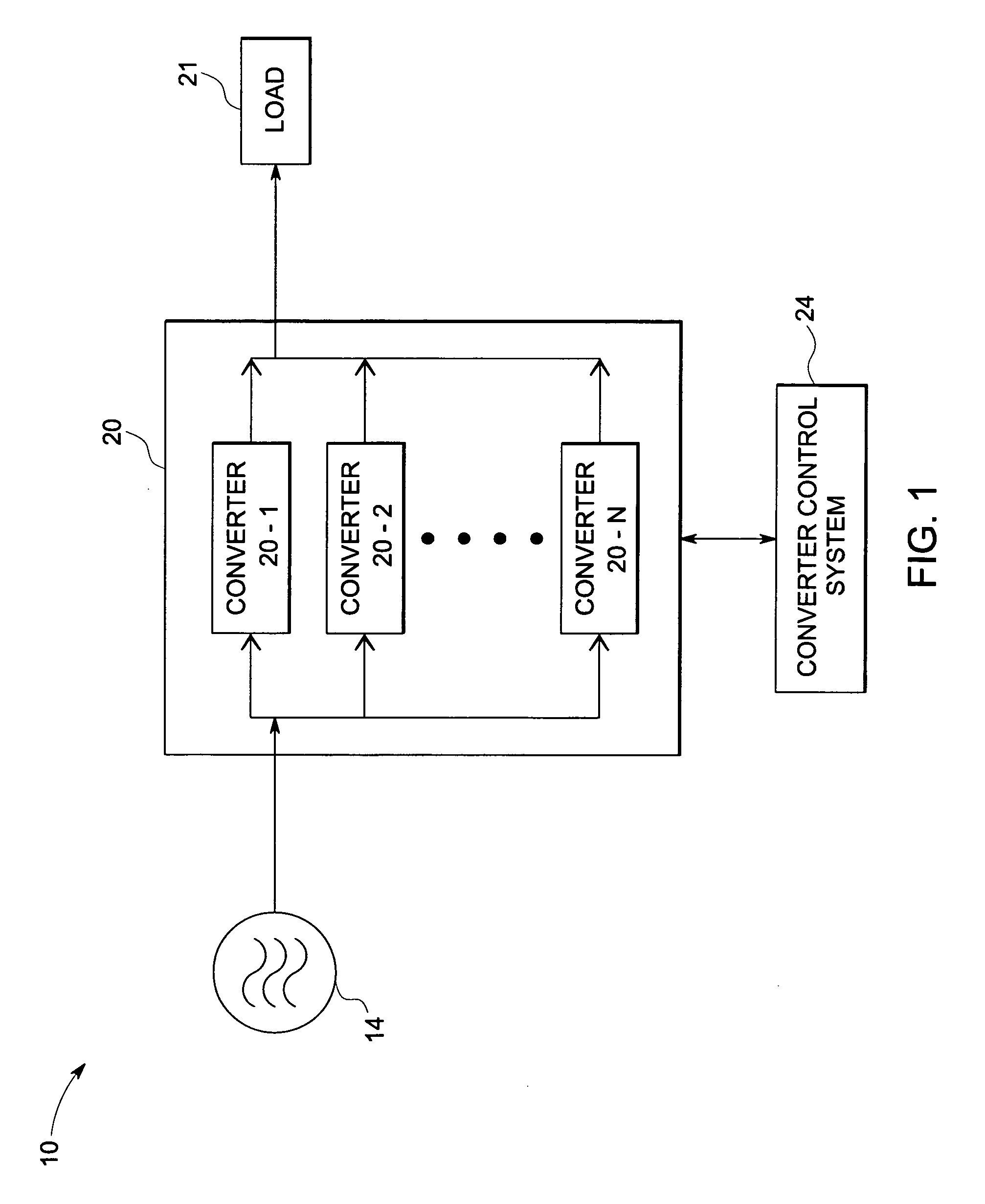
[0019]FIG. 1 is a block diagram of one embodiment of a power system 10 implemented according to one aspect of the invention. Power system 10 is configured for supplying power to a load 21. Each block is described in further detail below.

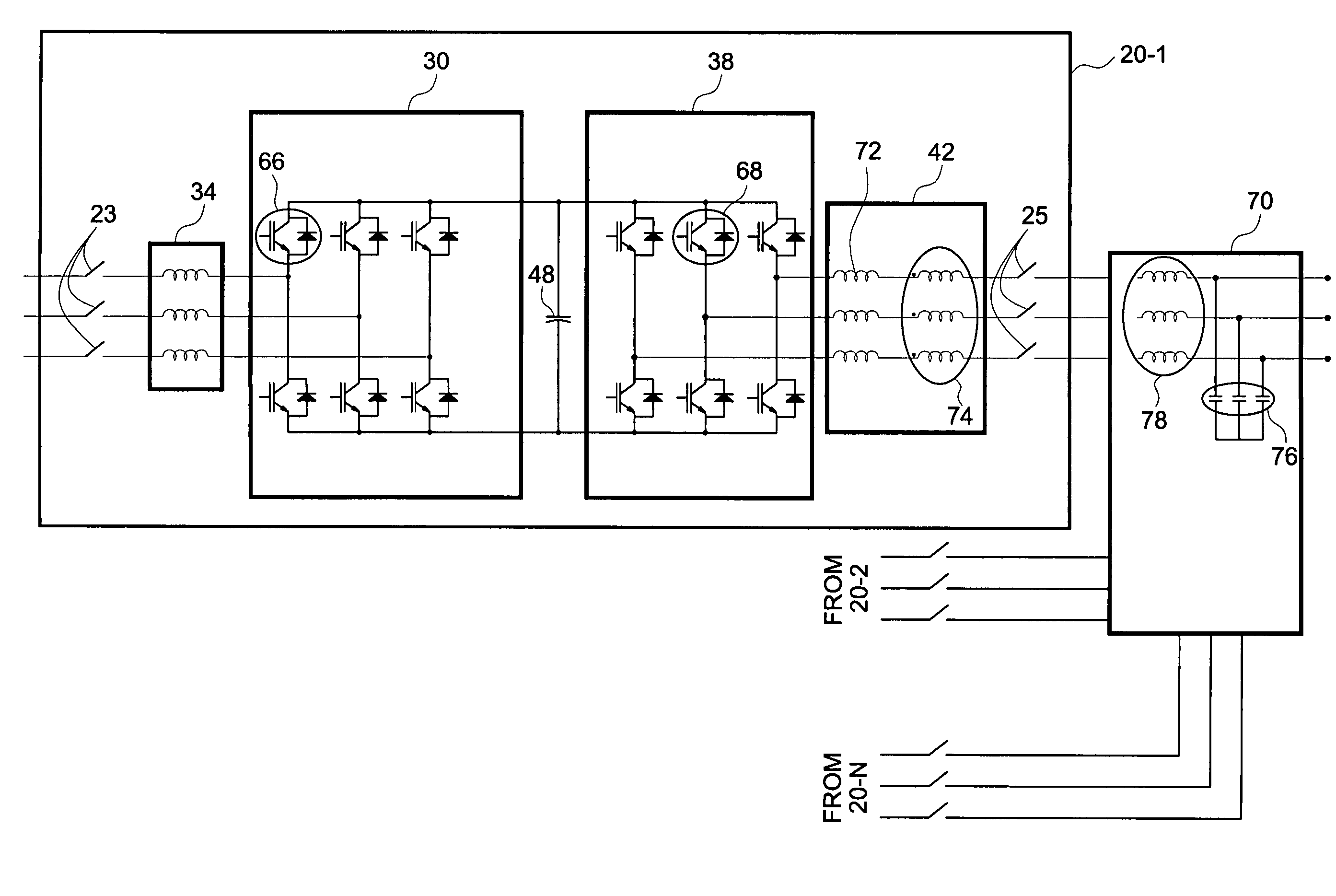
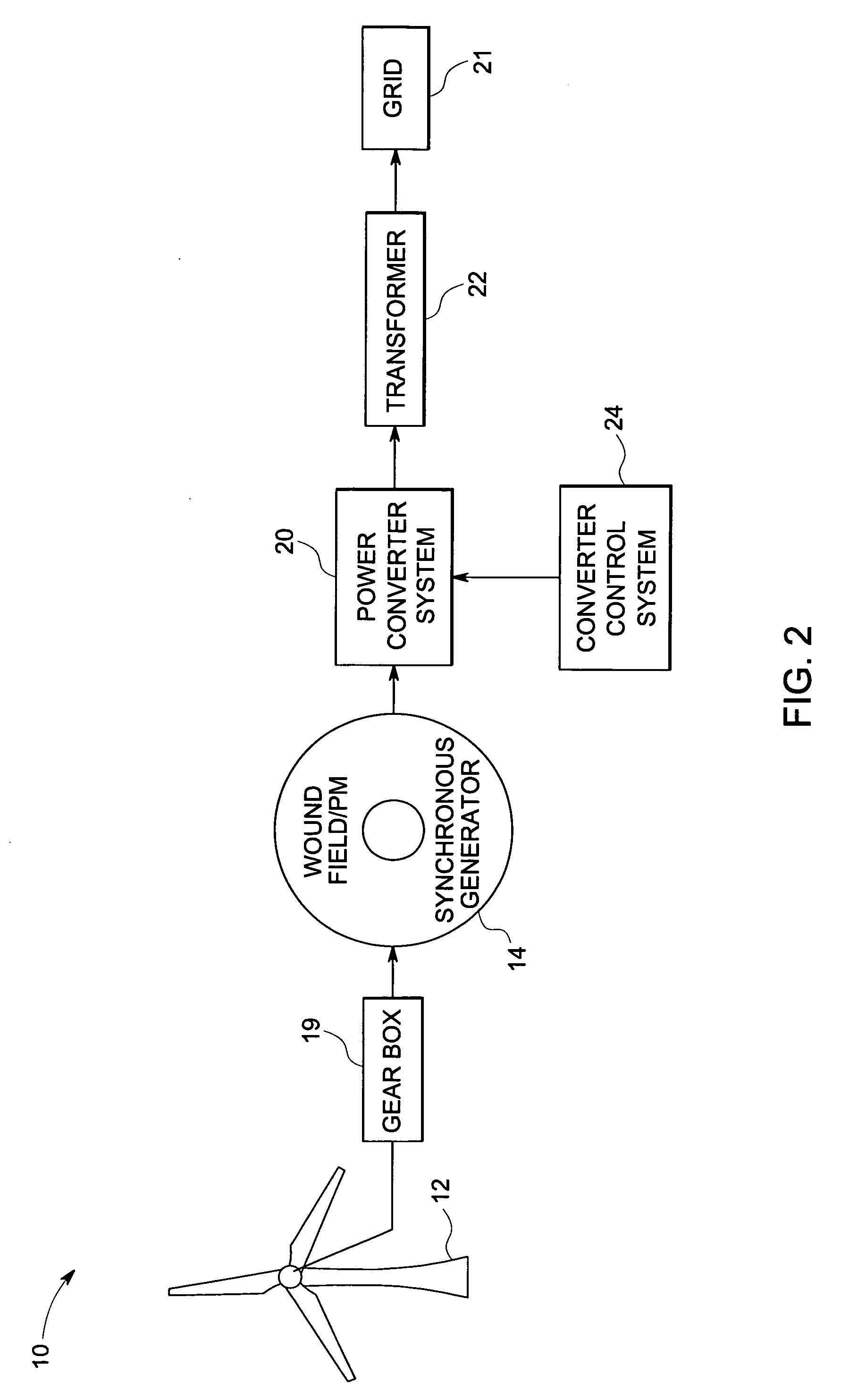
[0020] A generator source 14 is configured to generate an AC input power. The AC input power is provided to power converter system 20. The power converter system 20 comprises converter 20-1 through 20-N. The converters are coupled in parallel and configured to receive the AC input power from the generator source 14. The power converter system 20 is configured to convert the AC input power to an output power. The output power is provided to load 21. In one embodiment, the output power has a fixed frequency. Loads may include motors, power grids, and resistive loads, for example. Although grids are traditionally suppliers of power, in some wind turbine system embodiments, wind turbine power is supplied to a utility grid which acts as a load in such em...


PUM


Abstract

A power system for providing an output power to a load is provided. The system comprises a generator configured to generate an alternating current input power and an power converter system coupled to the generator and configured to generate an output power and provide the output power to the load through at least one transformer. The system further comprises a converter control system coupled to the converter system and configured to drive the converter system in an interleaved pattern to reduce harmonic components in the output power and the alternating current input power.

Description

BACKGROUND [0001] The invention relates generally to power converter systems and more specifically to a method and system for operating a power converter system in an interleaved manner. [0002] Many devices, such as wind turbines, include power converter systems. A power converter system is typically used to convert an input voltage, which may be fixed frequency alternating current, variable frequency alternating current, or direct current, to a desired output frequency and voltage level. A converter system usually includes several power semiconductor switches such as insulated gate bipolar transistors (IGBTs), integrated gate commutated thyristors (IGCTs or GCTs), or MOSFETs that are switched at certain frequencies to generate the desired converter output voltage and frequency. The converter output voltage is then provided to various loads. Loads as used herein are intended to broadly include motors, power grids, and resistive loads, for example. [0003] Typically, power converter s...

Claims


Application Information

Patent Timeline
Patent Type & Authority Applications(United States)
IPC IPC(8): H02M1/12
CPCH02M1/12H02M5/4585H02J3/386Y02E10/763H02J2300/28H02J3/381Y02E10/76
Inventor ZHANG, RICHARDWANG, CHANGYONGLI, LEILYONS, JAMESTAN, ZHUOHUIRITTER, ALLEN
Owner GENERAL ELECTRIC CO
Why Eureka
Try Eureka