Ultrasonic diagnosis apparatus

a diagnostic apparatus and ultrasonic technology, applied in ultrasonic/sonic/infrasonic image/data processing, instruments, tomography, etc., to achieve the effect of reducing the amount of unnecessary signal components, preventing excessive suppression, and being less vulnerable to effects

Active Publication Date: 2016-05-17
FUJIFILM HEALTHCARE CORP
View PDF12 Cites 0 Cited by
  • Summary
  • Abstract
  • Description
  • Claims
  • Application Information

AI Technical Summary

Benefits of technology

[0007]An advantage of the present invention is to prevent excessive suppression with respect to a reception signal while reducing an unnecessary signal component contained in the reception signal.
[0008]In accordance with an aspect of the invention, there is provided an ultrasonic diagnosis apparatus including an array transducer which is composed of a plurality of transducer elements, a delay processing unit which performs delay processing with respect to a plurality of element reception signals output from the plurality of transducer elements, a summing processing unit which performs summing processing with respect to the plurality of element reception signals having been subjected to the delay processing and outputs a reception signal, a circuit which extracts a sign data array formed of a plurality of sign data items arranged in an element arranging direction, from the plurality of element reception signals having been subjected to the delay processing but not having been subjected to the summing processing, an evaluation value computing unit which computes an evaluation value based on a direct current vicinity component contained in the sign data array, and a gain adjustment unit which adjusts gain of the reception signal by using the evaluation value.
[0009]With the above structure, because a plurality of sign data items extracted from a plurality of element reception signals are used as a basis for computing an evaluation value; i.e., because a plurality of amplitude values of the plurality of element reception signals are not directly used as a basis for computing the evaluation value, there can be realized an evaluation value computation which is less vulnerable to the effects of the side-lobe component or the like, or which is less dependent on the side-lobe component. Accordingly, because excessive suppression of the reception signal caused by the side-lobe component or the like can be prevented, the possibility of generation of dark portions resulting from a strong reflector at different positions on an ultrasonic diagnosis image can be prevented or reduced. Further, with the above structure, because not only the direct current (DC) component contained in the sign data array but also the alternating current component in the vicinity of the direct current region can be used as a basis for computation of the evaluation value, even if there is a fluctuation of the main-lobe component, an evaluation value computation which is less vulnerable to such a fluctuation can be achieved. As a result, because excessive suppression of the reception signal resulting from the fluctuation of the main-lobe component can be prevented, occurrence of an “uneven phenomenon” in which a large number of fine dark portions are generated in a homogeneous medium (a tissue having uniformity) on an ultrasonic diagnosis image can be prevented or reduced. As described above, according to the above structure, it is also possible to make use of the advantages of the conventional GCF and SCF, while at the same time mitigating the disadvantages thereof. Accordingly, signal processing with a high practical value can be provided. The direct current vicinity component described above corresponds to a portion of the power spectrum on the lower side, and refers to a power component existing within a section on the frequency axis from the frequency zero (DC) to a predetermined frequency. Here, the predetermined frequency is generally set as a low frequency in the vicinity of the direct current region on the frequency axis, and it is desirable to variably set the predetermined frequency automatically or by a user.
[0010]Preferably, the ultrasonic diagnosis apparatus further includes a control unit which sets a receiving aperture which changes dynamically, with respect to the array transducer, and the evaluation value computing unit computes the evaluation value by standardizing the direct current vicinity component by using the number of transducer elements forming the receiving aperture. With the size variation of the receiving aperture, the number of reception signals which are generated; i.e., the operating transducer elements, changes, in association with which the power of the direct current vicinity component changes. Accordingly, in order to prevent inadvertent change of the gain by means of a change of the receiving aperture size, standardization of the number of operating transducer elements is desired.
[0011]Preferably, the ultrasonic diagnosis apparatus further includes a function generating unit which generates a weighting function formed of a plurality of weight values, and a weighting processing unit which performs weighting processing with respect to the plurality of element reception signals, by using the weighting function, and the evaluation value computing unit computes the evaluation value in accordance with the weighting function. Because the degree of contribution or the degree of influence of the individual element reception signals in the phase alignment and summing processing changes due to the weighting processing with respect to the plurality of element reception signals, it is desirable to take into consideration the weighting function; i.e., a plurality of weight values, at the time of computing the evaluation value. Preferably, the weighting processing unit is provided between the delay processing unit and the summing processing unit, and the circuit which extracts the sign data array extracts the sign data array from the plurality of element reception signals having been subjected to the delay processing but having not been subjected to the weighting processing. With this structure, the evaluation value can be computed appropriately, even when a negative value is included in the plurality of weight values.
[0012]Preferably, the circuit which extracts the sign data array extracts the sign data array by extracting a plurality of sign bits from the plurality of element reception signals. Alternatively, the circuit which extracts the sign data array includes a circuit which extracts an amplitude profile formed of a plurality of instantaneous amplitude values from the plurality of element reception signals, and a circuit which performs binarization processing with respect to the amplitude profile, with a hysteresis property. With the binarization processing having a hysteresis property, natural processing which does not depend on unstable amplitude behavior in the vicinity of the baseline can be performed. As is known, the binarization processing having a hysteresis property refers to processing in which separate threshold values are used for the rise and fall of the waveform. Further, it is also possible to apply ternarization processing in which signals in the vicinity of the baseline are converted to zero.

Problems solved by technology

However, both methods described above have advantages and disadvantages.

Method used


Image

  • Ultrasonic diagnosis apparatus
  • Ultrasonic diagnosis apparatus
  • Ultrasonic diagnosis apparatus

Examples


Embodiment Construction

[0025]A preferred embodiment of the present invention will be described in detail with reference to the accompanying drawings.

[0026](1) Explanation of GCF Method and SCF Method

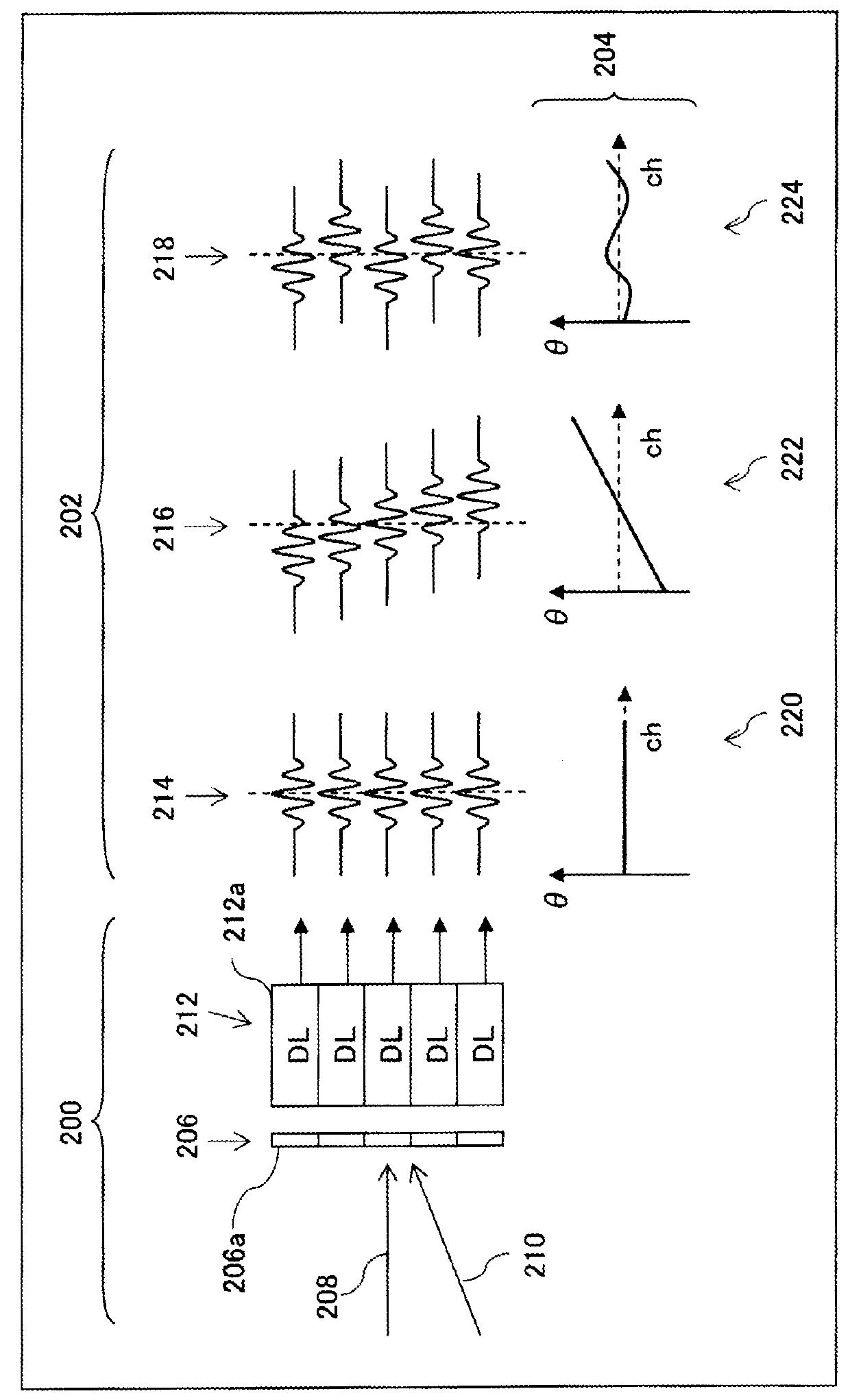
[0027]FIG. 1 illustrates the function of a receiving beam former in an ultrasonic diagnosis apparatus. The receiving beam former constitutes a receiving unit, or a phase alignment and summing processing unit. Reference numeral 200 represents processing of receiving waves. An array transducer 206 is composed of a plurality of transducer elements 206a arranged indicates a reflection wave (a main-lobe component) from a receiving focus point, and reference numeral 210 indicates an unnecessary wave component (which is, in this example, a side-lobe component from a strong reflector). The receiving beam former includes a delay line array 212 for delay processing. The delay line array 212 is composed of a plurality of delay lines 212a. The delay times of the individual delay lines 212a are dynamically set in a variabl...


PUM


Abstract

There is provided an ultrasonic diagnosis apparatus capable of reducing an unnecessary signal component in a reception signal. A plurality of sign bits arranged in the channel direction are extracted from a plurality of element reception signals. A binarization circuit applies binarization processing to the plurality of sign bits to thereby generate a sign data array. An evaluation value computing unit computes an evaluation value (GSCF) based on a DC vicinity component contained in the sign data array on the frequency axis. This evaluation value is used to adjust the gain of the reception signal in a multiplier. With application of the binarization processing, excessive reduction of the reception signal can be prevented. Further, as the DC vicinity component is referenced, the side-lobe component can be appropriately reduced even if a certain degree of fluctuation exists in the main-lobe component.

Description

BACKGROUND[0001]1. Technical Field[0002]The present invention relates to an ultrasonic diagnosis apparatus, and more particularly to a technique of reducing an unnecessary or undesired signal component in a reception, signal.[0003]2. Background Art[0004]Ultrasonic diagnosis apparatuses are apparatuses which form an ultrasonic diagnosis image by transmitting and receiving ultrasound to and from a living organism. In order to increase the image quality of the ultrasonic diagnosis image, it is desirable to reduce an unnecessary signal component contained in a reception signal; i.e., a side-lobe component, a grating lobe component, a noise component, or the like.[0005]Two methods have been proposed for reducing or suppressing an unnecessary signal component contained in a reception signal after phase alignment and summing processing: one is a first method (a GCF method) for suppressing a reception signal by using a factor called a GCF (Generalized Coherence Factor) (see Pai-Chi Li, et a...

Claims


Application Information

Patent Timeline
Patent Type & Authority Patents(United States)
IPC IPC(8): A61B8/08G01S7/52G10K11/34G01S15/89
CPCA61B8/5269G01S7/52033G01S7/52047G01S7/52049G01S7/52077G10K11/346G01S15/8915
Inventor HISATSU, MASANORI
Owner FUJIFILM HEALTHCARE CORP
Why Eureka
Try Eureka