Noise suppression device
a technology of noise suppression and noise reduction, which is applied in the direction of sound producing devices, speech analysis, ear treatment, etc., can solve the problems of reduced voice recognition rate, reduced call voice, and inability to calculate the suppression amount correctly, so as to prevent excessive suppression and high-quality noise suppression
- Summary
- Abstract
- Description
- Claims
- Application Information
AI Technical Summary
Benefits of technology
Problems solved by technology
Method used
Image
Examples
embodiment 1
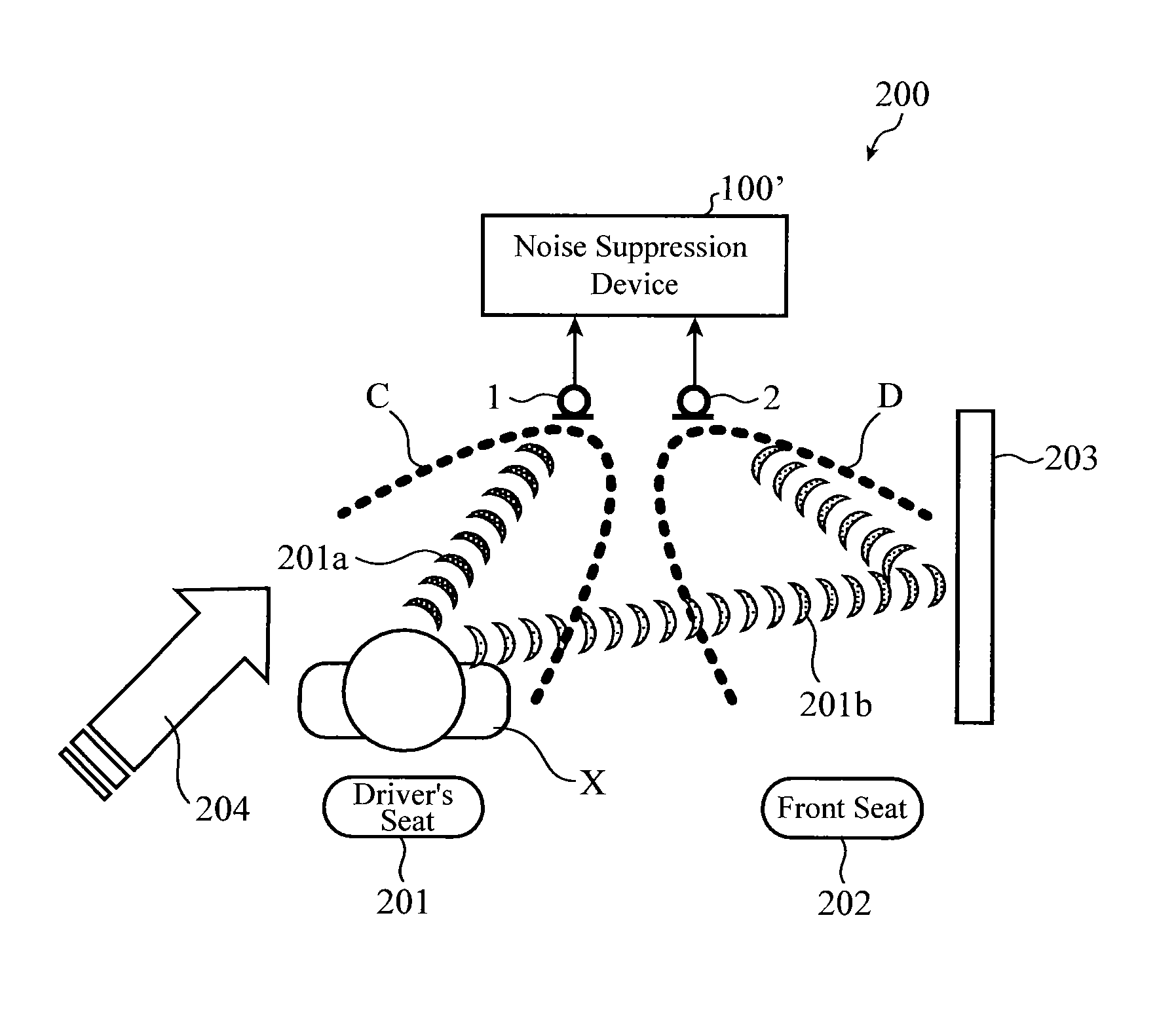
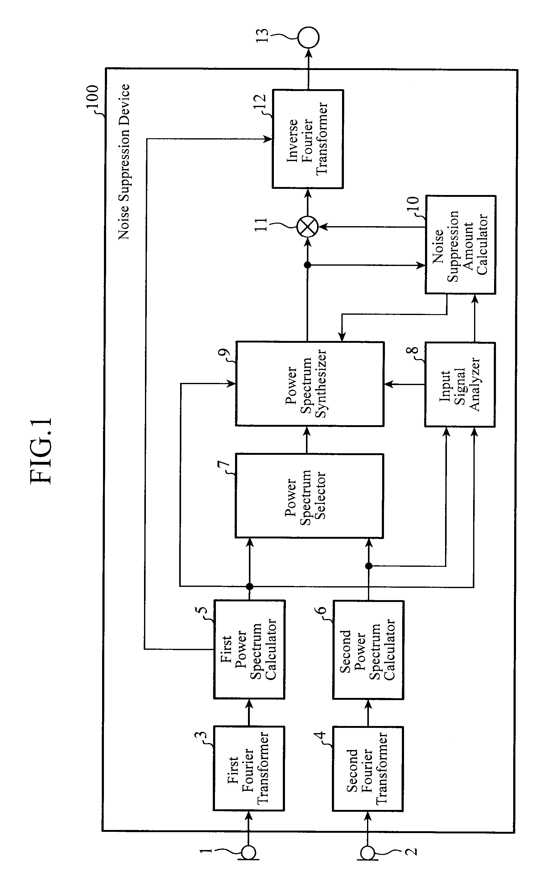
[0028]FIG. 1 is a block diagram showing the structure of a noise suppression device in accordance with Embodiment 1. The noise suppression device 100 to which a first microphone 1 and a second microphone 2 which are input terminals are connected is comprised of a first Fourier transformer 3, a second Fourier transformer 4, a first power spectrum calculator 5, a second power spectrum calculator 6, a power spectrum selector 7, an input signal analyzer 8, a power spectrum synthesizer 9, a noise suppression amount calculator 10, a power spectrum suppressor 11, and an inverse Fourier transformer 12. An output terminal 13 is connected, as a subsequent stage, to the inverse Fourier transformer 12.
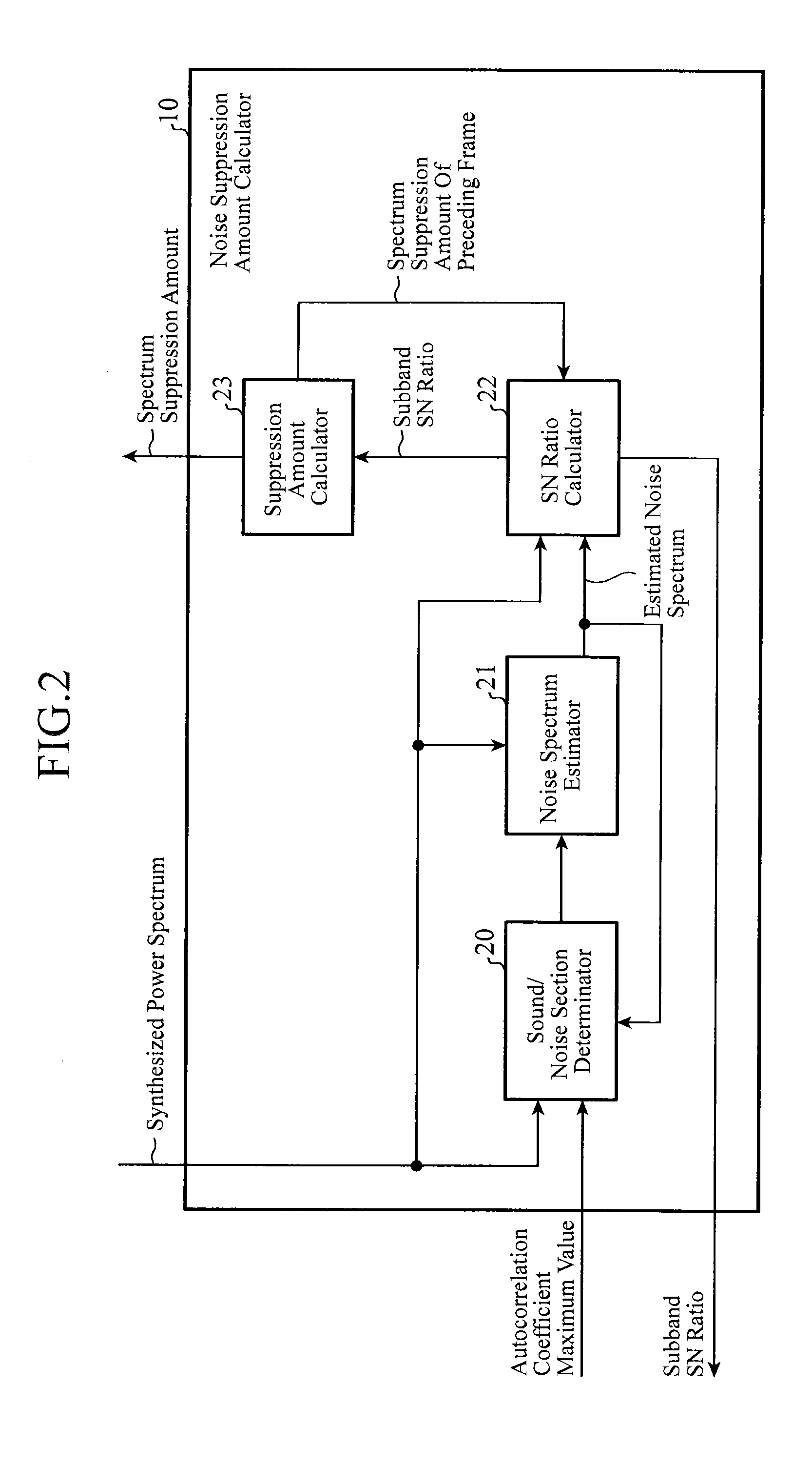
[0029]FIG. 2 is a block diagram showing the structure of the noise suppression amount calculator of the noise suppression device in accordance with Embodiment 1. As shown in FIG. 2, the noise suppression amount calculator 10 is comprised of a sound / noise section determinator 20, a noise spectrum e...
embodiment 2
[0063]In above-mentioned Embodiment 1, the process of changing whether or not (ON / OFF) to carry out the power spectrum synthesis using the above-mentioned equation (8) is carried out on the basis of a comparison between the average snrave(λ) of the subband SN ratios, which is shown in the above-mentioned equation (9), and the predetermined threshold SNRTH. As an alternative, for example, instead of the process of replacing a spectral component, a process of weighted-averaging a synthesized spectrum candidate and a first power spectrum by using this average snrave(λ) as an index showing the degree of sound likeness of the input signal can be carried out, as a power spectrum synthesizing process with a more-continuous change, for a section in which a sound section transitions to a noise section and for a section (transition section) in which a noise section transitions to a sound section, as shown in equation (17) which will be shown below. In Embodiment 2, this structure will be show...
embodiment 3
[0066]Although the structure of setting the value of the limiter A to a predetermined constant in the above-mentioned equation (4) is shown in above-mentioned Embodiment 1, a structure of switching between two or more constants according to an index showing the degree of sound likeness of the input signal to use a constant selected as the value of the limiter, or controlling the value of the limiter by using a predetermined function is shown this Embodiment 3. For example, when the maximum value ρM—max(λ) of the autocorrelation coefficient in the above-mentioned equation (7), as the index showing the degree of sound likeness of the input signal, i.e., a control factor of the state of the input signal, is large, i.e., when the periodical structure of the input signal is clearly seen (there is a high possibility that the input signal is a sound), the value can be set to a large one; otherwise, the value can be set to a small one. Further, the maximum value ρM—max(λ) of the autocorrela...
PUM
 Abstract
Description
Claims
Application Information
 - R&D
- Intellectual Property
- Life Sciences
- Materials
- Tech Scout
- Unparalleled Data Quality
- Higher Quality Content
- 60% Fewer Hallucinations
Browse by: Latest US Patents, China's latest patents, Technical Efficacy Thesaurus, Application Domain, Technology Topic, Popular Technical Reports.
© 2025 PatSnap. All rights reserved.Legal|Privacy policy|Modern Slavery Act Transparency Statement|Sitemap|About US| Contact US: help@patsnap.com


