Belt band conveyor

a belt band and belt technology, applied in the direction of conveyor parts, rollers, transportation and packaging, etc., can solve the problems of long useful life of belt materials, difficult deflection drums and drive drums of curved belts, and difficult lathering or grinding of drum coatings in order to achieve convexity, etc., to achieve simple and quick assembly, improve or optimal force or torque transfer

Inactive Publication Date: 2016-09-13
AXMANN FOERDERSYST
View PDF28 Cites 5 Cited by
  • Summary
  • Abstract
  • Description
  • Claims
  • Application Information

AI Technical Summary

Benefits of technology

[0011]It is therefore an object of the invention to provide a belt band conveyor of the type mentioned initially, in which the above disadvantages are avoided, particularly in which simple and quick assembly and disassembly of the roller segments, if applicable also of further components disposed on the shaft, also for the purpose of their replacement, is just as well possible as improved or optimal transfer of force or torque.
[0012]These and the other objects are accomplished, in surprisingly simple manner, by a belt band conveyor according to the invention, particularly in that the roller segments are set onto the shaft in axially releasable manner, so that the roller segments can be axially pulled off or pulled out of the shaft, and that the inside circumference contour of each roller segment and the outside circumference contour of the shaft assigned to it are structured to be coordinated with one another in such a manner that each roller segment is connected with the shaft, preferably with slight radial play, with shape fit to prevent twisting about the axis of rotation, so that when the shaft turns about the axis of rotation, in a direction of rotation, the roller segments also turn about the axis of rotation, in this direction of rotation.

Problems solved by technology

Furthermore, the skid resistance serves to reduce the tension of the belt, and this tension reduction can lead to a longer useful lifetime of the belt material.
The deflection drum and drive drum are similar in structure at the manufacturers, and have been complicated, in unchanged manner, for many years.
Lathing off or grinding off of the drum coating, in order to achieve the convexity, is also complicated.
Deflection drums and drive drums of curved belts are particularly complicated.
All the embodiments have in common that they are very complicated in terms of production.
Often, the drum already makes up a significant percentage of the production costs of a belt conveyor.
These designs are also relatively complicated and correspondingly expensive.
Furthermore, transfer of force and moment by the roller segments that can rotate about the shaft independent of one another is not possible, or possible only insufficiently.

Method used


Image

  • Belt band conveyor
  • Belt band conveyor
  • Belt band conveyor

Examples


Embodiment Construction

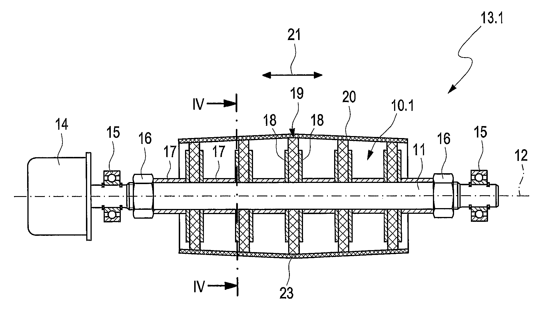
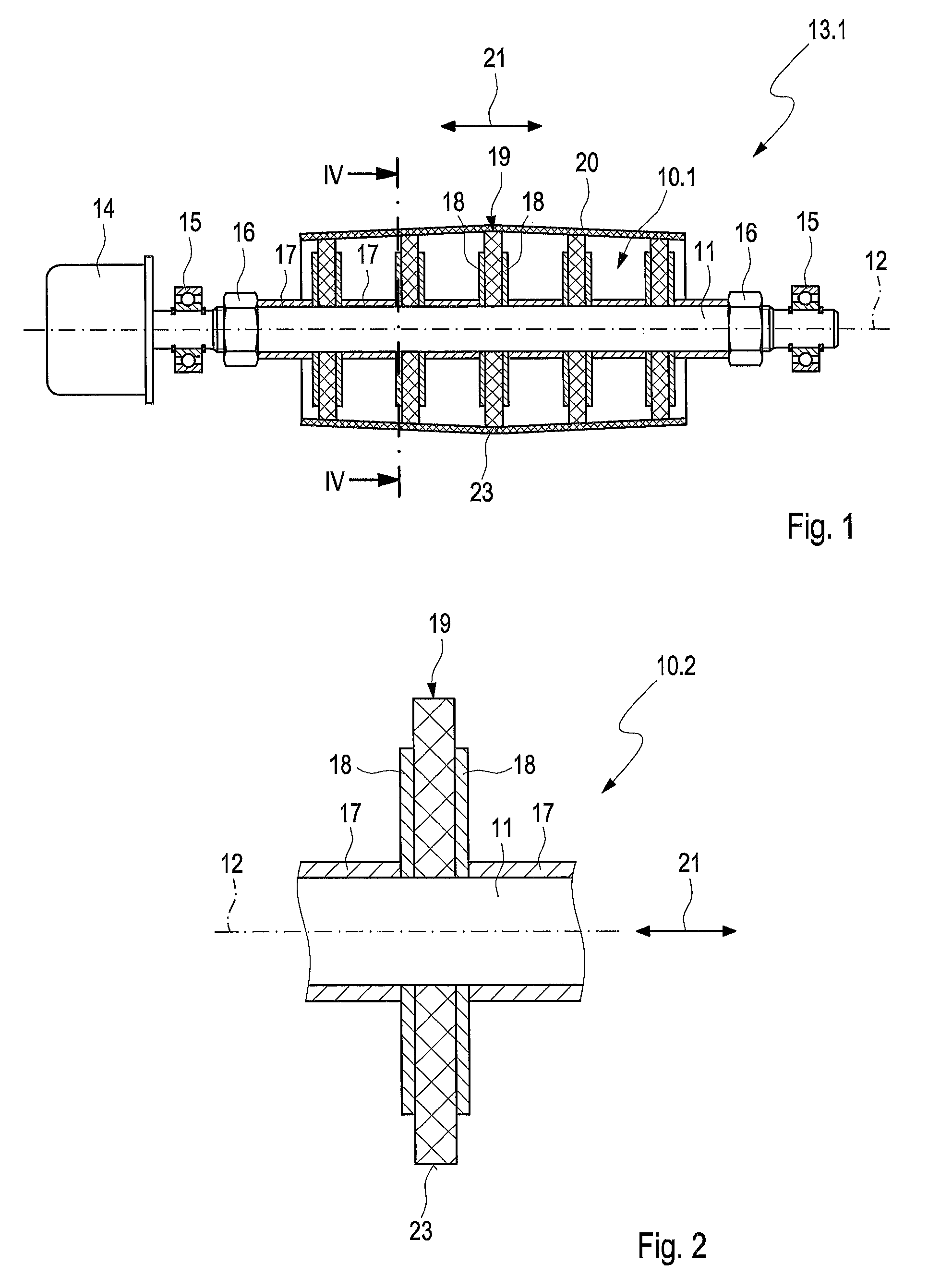
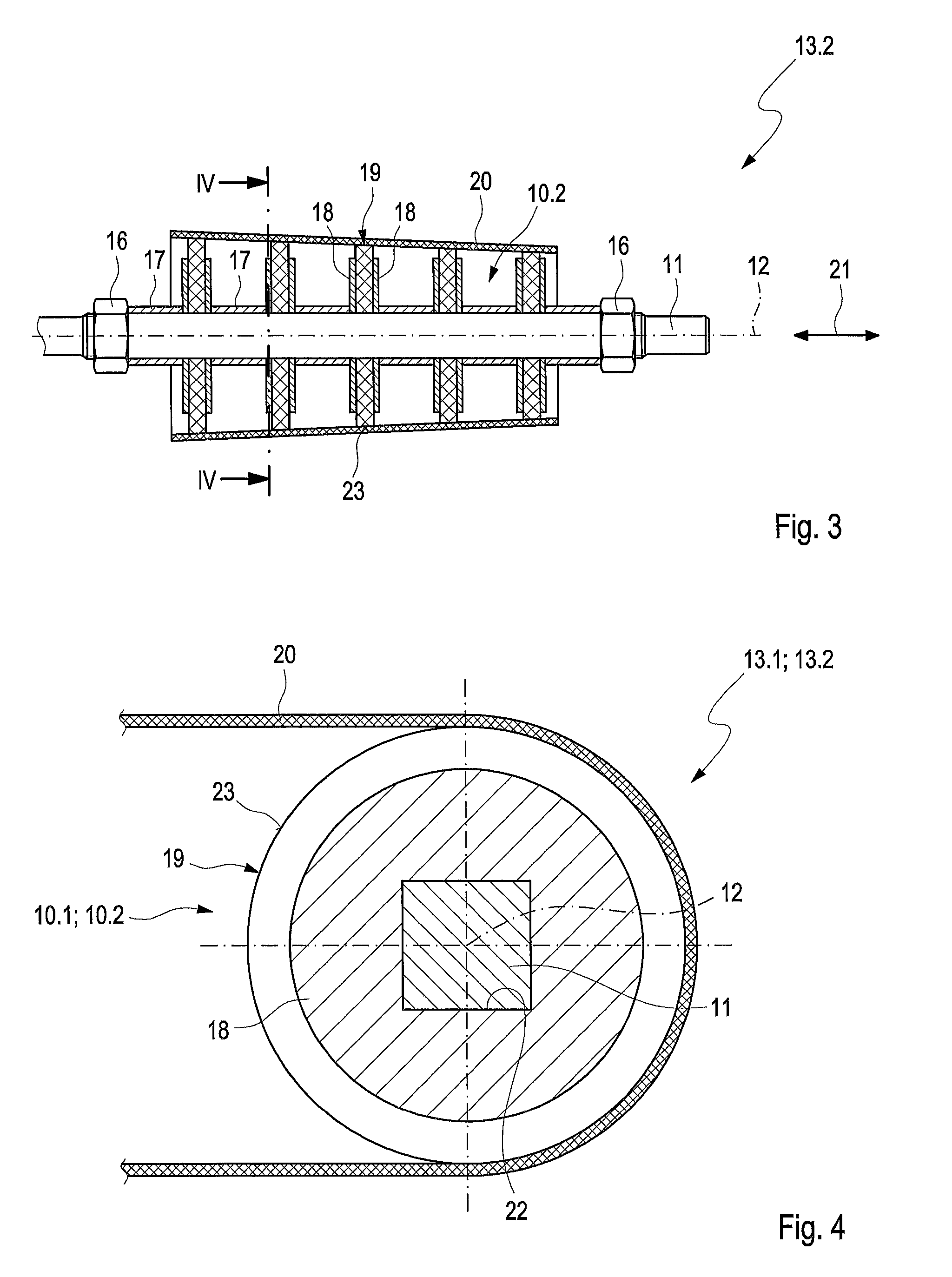
[0042]Referring now in detail to the drawings, each belt band conveyor 13.1, 13.2 shown in FIGS. 1 and 3 comprises an endless conveyor belt band 20 that is guided over deflection friction rollers as well as over drive friction rollers and deflection friction rollers 10.1, 10.2, with its lower belt, for deflecting or driving the conveyor belt band 20. In the figures, a drive friction roller and deflection friction roller 10.1, 10.2 can be driven or is driven by means of a drive motor, for friction-fit drive and deflection of the respective conveyor belt band 20. In FIG. 1, an electric drive motor 14 is shown as an example. Without the drive motor and without the friction roller being drivable, the friction roller would be a pure deflection friction roller. In FIG. 3, no drive motor is shown. Nevertheless, even there a drive friction roller and deflection friction roller 10.2 that can be driven by means of a drive motor is shown there. There, too, the friction roller would be a pure d...


PUM


Abstract

A belt band conveyor has an endless conveyor belt band guided over deflection and / or drive friction rollers, for deflecting and / or driving the conveyor belt band. Each roller includes an axially-extending shaft. At least three roller segments are releasably mounted on the shaft, axially apart from one another, so as to rotate about a rotational axis extending axially in the longitudinal direction, Each roller segment has an inside circumference contour and a friction surface on its radial outside circumference engaging on the lower belt with friction fit. The inside circumference contour of each roller segment and the outside circumference contour of the shaft are structured so that each roller segment is connected with the shaft with shape fit to prevent twisting about the rotational axis. When the shaft turns about the rotational axis, in a rotational direction, the roller segments also turn about the rotational axis, in this rotational direction.

Description

CROSS REFERENCE TO RELATED APPLICATIONS[0001]Applicant claims priority under 35 U.S.C. §119 of German Application No. 10 2014 119 043.2 filed Dec. 18, 2014, the disclosure of which is incorporated by reference.BACKGROUND OF THE INVENTION[0002]1. Field of the Invention[0003]The invention relates to a belt band conveyor having an endless conveyor belt band, preferably motor-driven, that is guided over deflection friction rollers and / or over drive friction rollers, preferably motor-driven, with its lower belt, for deflecting and / or driving the conveyor belt band.[0004]The rollers each comprise a shaft that extends in a longitudinal direction, which shaft has an outside circumference contour, wherein at least three roller segments are mounted on the shaft, which segments are disposed axially adjacent, in each instance, in the longitudinal direction, at an axial distance from one another, and wherein each roller segment of the roller segments is mounted so as to rotate about an axis of r...

Claims


Application Information

Patent Timeline
Patent Type & Authority Patents(United States)
IPC IPC(8): B65G23/12B65G21/16B65G23/04B65G39/16
CPCB65G39/16B65G39/04B65G39/071
Inventor AXMANN, NORBERT
Owner AXMANN FOERDERSYST
Why Eureka
Try Eureka