Combination of the chucking device and a drill and a chucking device for a drill with cutting tips on both ends

a chucking device and drill technology, applied in the field of can solve the problems of unavoidable manufacturing tolerances, increased external diameter, and inability to use chucking devices for drill tools, and achieve the effect of easy and safe clamping

Inactive Publication Date: 2014-03-18
KENNAMETAL INC
View PDF54 Cites 4 Cited by
  • Summary
  • Abstract
  • Description
  • Claims
  • Application Information

AI Technical Summary

Benefits of technology

[0008]The object may be achieved in at least one possible embodiment of a drill or cutting tool having a two-part adapter sleeve featuring shells that can be pivoted in relation to each other and that may be kept together captively in the process. The one chucking device featuring such a two-part adapter sleeve makes it possible to surround that part of the drill tool with the adapter sleeve, where the external diameter of the drill tool is constant. Its inner diameter can then also be kept constant over the sleeve length. This way, a positive—and in a clamped and braced state non-positive—connection over the length of the drill tool back enclosed by the adapter sleeve is achieved. This way, drill tools featuring drill diameters that increase towards the drill tips can be clamped easily and safely. For this purpose, the adapter sleeve housing the drill tool—in which the drill tool has then already been inserted—is centered in a chucking device, for instance a chuck, of a machine tool and non-positively secured.
[0009]The adapter sleeve comprises two shells that can be pivoted in relation to each other about a pivoting axis. Swinging open the shells allows the quick and simple assembly of the drill tool. In this connection, the pivoting axis may run parallel to the longitudinal axis of the sleeve. In this version featuring a pivoting axis that runs parallel to the longitudinal axis of the sleeve, the shells that can be pivoted in relation to each other are connected with one another with their facing longitudinal sides.
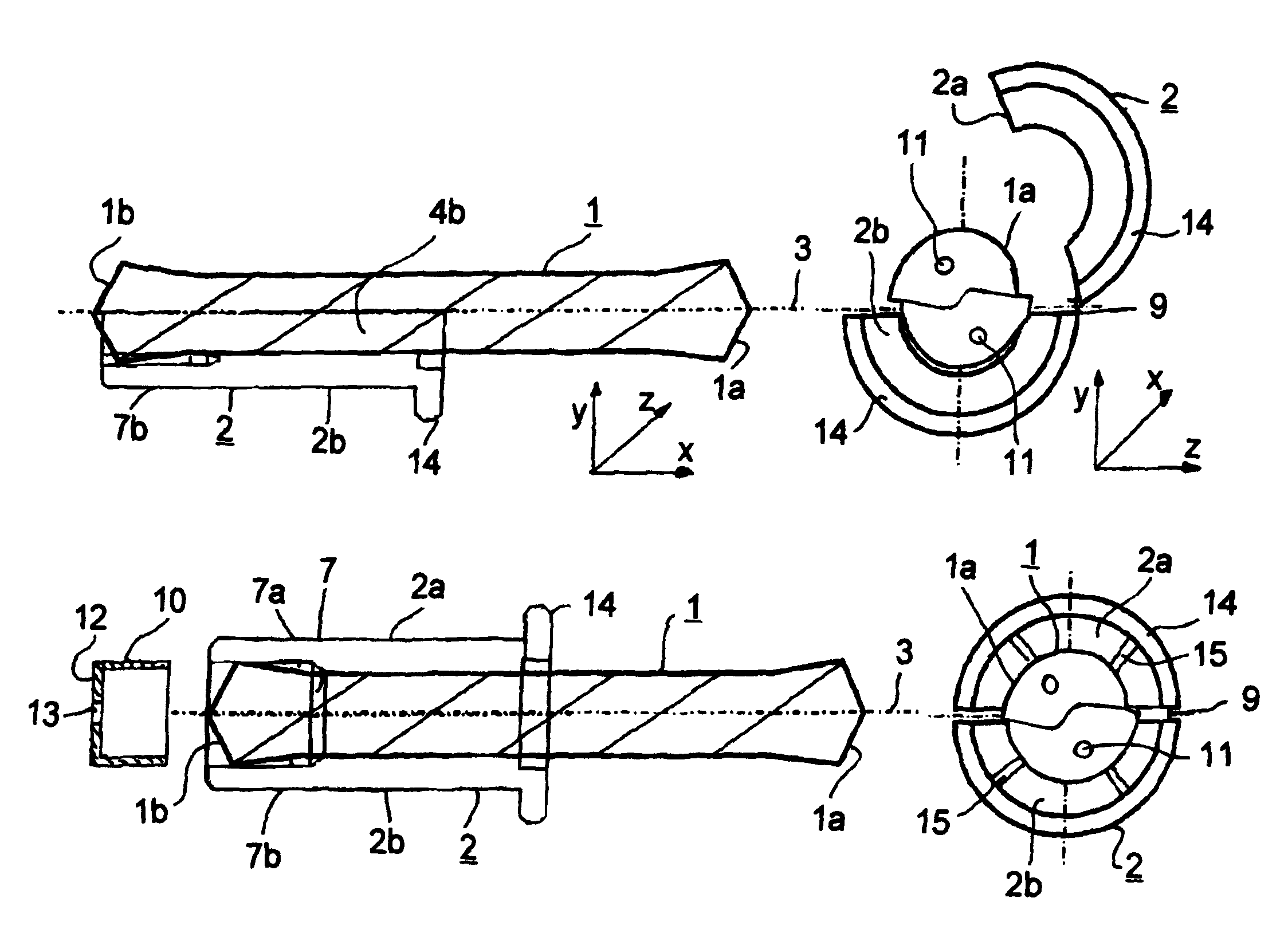
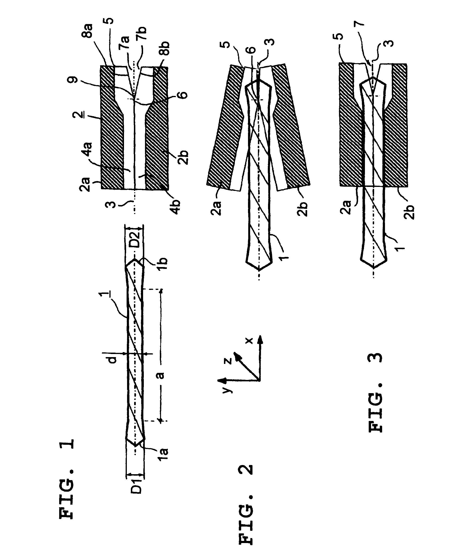
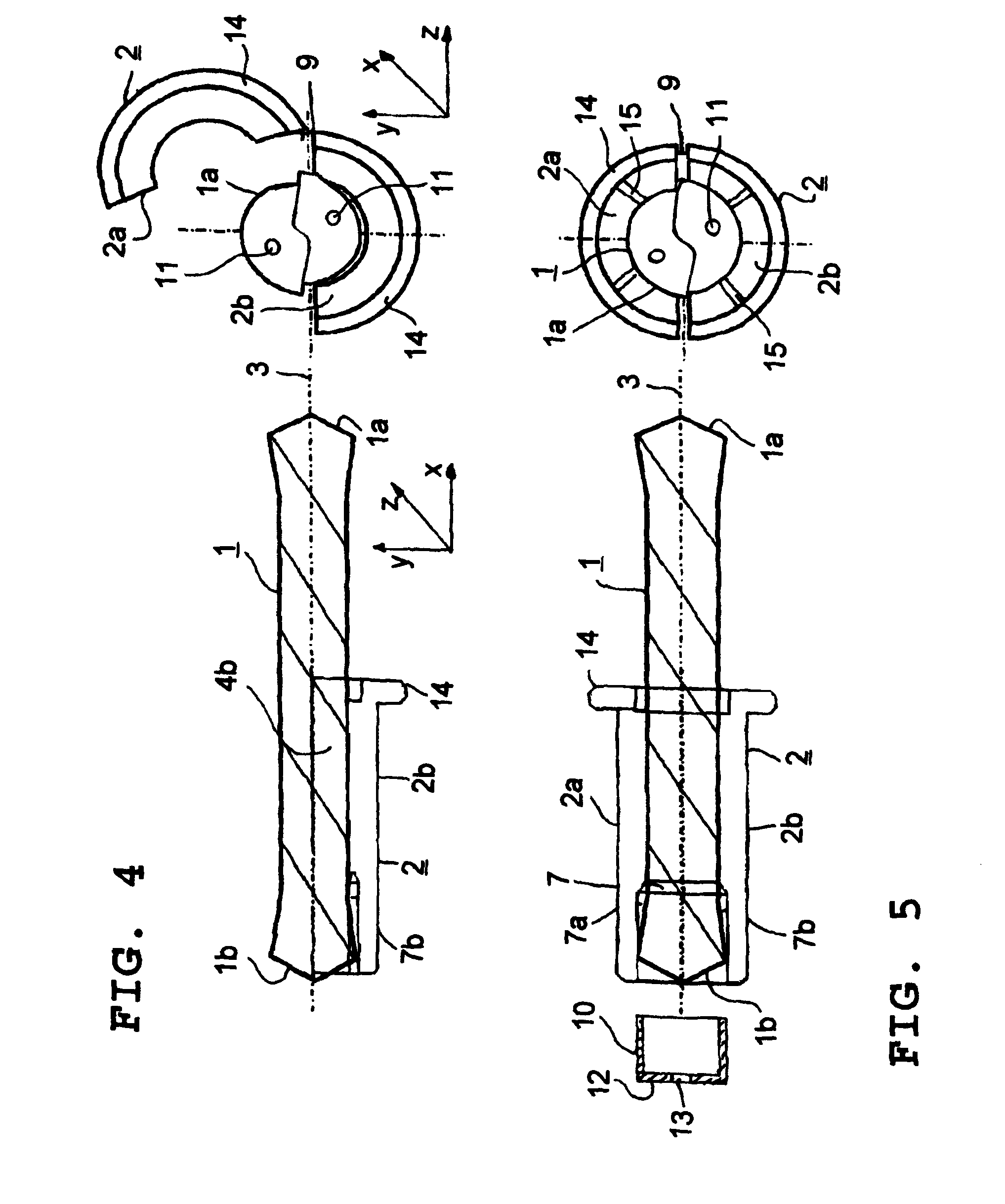
[0010]However, according to at least one possible embodiment, the pivoting axis runs crosswise to the longitudinal axis of the sleeve. In this version the two shells can be opened at one end of the sleeve, about wedge or V-shaped, about a pivoting axis there. This can for instance be achieved by transversely running recesses at a shell or by forming a dovetail-like folding wedge at both shells. This version promotes a simple and safe assembly of the drill tool.
[0014]The elastic connecting sleeve may be embodied with two walls by forming a sealing lip on the inside and on the outside of the sleeve. Furthermore, the connecting sleeve features a ring-shaped sealing groove, which according to at least one possible embodiment runs at the perimeter of the front edge of the sleeve end. In the double-walled embodiment of the connecting sleeve this elastic circumferential groove forms the connecting post between the two sealing lips. By way of this embodiment the elastic connecting sleeve fulfills a dual function. On the one hand, the connecting sleeve forms the elastic pivoting connection provided for the ability of the connecting sleeve's two shells to pivot. On the other hand, the connecting sleeve can be deformed by means of a pressurized coolant or lubricant, such coolant or lubricant flowing against the sleeve end of the adapter sleeve—and there against the ring-shaped sealing groove—by producing an external seal effect against a chucking chamber wall, such as of an expansion chuck, and an inner seal effect against a sealing element, such sealing element being located in the adapter sleeve, or being attached to the drill end located in the adapter sleeve.
[0018]In one possible embodiment the adapter sleeve features a sleeve collar at one end of the sleeve. Said sleeve collar serves as arrester of the adapter sleeve at the chucking device, at the chuck or a corresponding tool holding fixture. Moreover, according to at least one possible embodiment, at least one slot-shaped recess is inserted in at least one of the shells. The so-called expansion membrane of the chucking device then compresses the adapter sleeve coaxially, assuring a reliable non-positive connection between the drill tool and the adapter sleeve as a result of clamping the adapter sleeve in the tool holding fixture.
[0021]Since, on the one hand, the two shells of the adapter sleeve can be pivoted in relation to each other and, on the other hand, are captively held together during such pivoting, especially by means of the elastic connection of the two shells, easy and reliable mounting as well as inserting in or joining of the drill tool with the adapter sleeve without error is promoted.

Problems solved by technology

However, said chucking device cannot be used for a drill tool, whose external diameter increases towards its drill ends or its drill tips.
The unavoidable manufacturing tolerances and the high production expenditures to insert the twisted flutes into the inner surface of the chucking device represent a disadvantage of the described embodiment.
Furthermore, inserting the twisted flute in the inner surface weakens the wall or the sleeve of the chucking device, thus either negatively influencing the stability, or requiring increased material and thus cost expenditures in thick-walled embodiments as compared to a design with smooth walls on the inside.
An additional disadvantage is that only drill tools featuring an ascending slope compatible with the inserted twisted flute can be clamped.
Cooling of the drill tip by means of the described coolant ducts is not possible in the case of small drill tool diameters.
On the one hand the reason for this is that inserting very thin coolant ducts is very complex in terms of production.

Method used


Image

  • Combination of the chucking device and a drill and a chucking device for a drill with cutting tips on both ends
  • Combination of the chucking device and a drill and a chucking device for a drill with cutting tips on both ends
  • Combination of the chucking device and a drill and a chucking device for a drill with cutting tips on both ends

Examples


Embodiment Construction

[0042]FIG. 1 shows a drill tool 1 comprising one drill tip 1a, 1b, each at every end, with a drill diameter D1 or D2 increasing towards the drill tips 1a, and 1b. Along a middle section of the drill a the diameter d of the drill tool 1 is constant. Diameter d may be 1 or d2, with D1=D2 or D1≠D2. An adapter sleeve 2 that serves to house the drill tool 1 is embodied in two parts. For this, the adapter sleeve 2 comprises two shells 2a, and 2b, that can be pivoted crosswise to the longitudinal axis of the sleeve running in the x direction.

[0043]As is evident from FIG. 1, the two shells 2a, and 2b, of the adapter sleeve 2 form a hollow cylinder featuring a cylindrical outer circumference. To accommodate the drill tool 1 said hollow cylinder develops suitable cylinder paths 4a, and 4b, of the shells 2a, or 2b respectively. The two shells 2a, 2b, can be opened wedge or V-shaped in y direction at a sleeve end 5 around a pivoting axis 6 running in z direction and thus crosswise to the longit...


PUM

PropertyMeasurementUnit
diameteraaaaaaaaaa
diameteraaaaaaaaaa
diameteraaaaaaaaaa

Abstract

A combination of a chucking device and a drill and a chucking device for a drill with cutting tips on both ends. The abstract of the disclosure is submitted herewith as required by 37 C.F.R. §1.72(b). As stated in 37 C.F.R. §1.72(b): A brief abstract of the technical disclosure in the specification must commence on a separate sheet, preferably following the claims, under the heading “Abstract of the Disclosure.” The purpose of the abstract is to enable the Patent and Trademark Office and the public generally to determine quickly from a cursory inspection the nature and gist of the technical disclosure. The abstract shall not be used for interpreting the scope of the claims. Therefore, any statements made relating to the abstract are not intended to limit the claims in any manner and should not be interpreted as limiting the claims in any manner.

Description

CONTINUING APPLICATION DATA[0001]This application is a Continuation-In-Part application of International Patent Application No. PCT / EP2006 / 011268, filed on Nov. 24, 2006,which claims priority from Federal Republic of Germany Patent Application No. 10 2005 056 440.2, filed on Nov. 26, 2005. International Patent Application No. PCT / EP2006 / 011268, was pending as of the filing date of this application. The United States was an elected state in International Patent Application No. PCT / EP2006 / 011268.BACKGROUND[0002]1. Technical Field[0003]This application concerns a chucking device for a drill tool, such as with one drill tip each at every end of the tool. In this connection, a drill tool means a drill intended to generate a boring with a constant diameter just as well as, for example, a step drill or a countersinking tool.[0004]2. Background Information[0005]Such a chucking device with a cylindrical adapter sleeve is known, for instance, from DE 203 16 350, U1. The adapter sleeve describ...

Claims


Application Information

Patent Timeline
Patent Type & Authority Patents(United States)
IPC IPC(8): B23B31/103B23B51/06
CPCB23B31/20B23B2231/2043B23B2231/36B23B2251/247B23B2260/126Y10T408/455Y10T279/17111Y10T279/17401Y10T279/17632Y10T279/17231Y10T279/17393B23B31/103
Inventor KAUPER, HERBERT RUDOLF
Owner KENNAMETAL INC
Why Eureka
Try Eureka