Pipe Coupling

Active Publication Date: 2008-11-27
UPONOR INNOVATION AB
View PDF15 Cites 4 Cited by
  • Summary
  • Abstract
  • Description
  • Claims
  • Application Information

AI Technical Summary

Benefits of technology

[0003]An object of the present invention is to provide a new and improved coupling. The coupling of the invention is characterized in that the coupling further comprises

Problems solved by technology

Widening of the slot-like opening is very hard and cumbersome and a tool for widening the opening is needed

Method used


Image

  • Pipe Coupling
  • Pipe Coupling
  • Pipe Coupling

Examples


Embodiment Construction

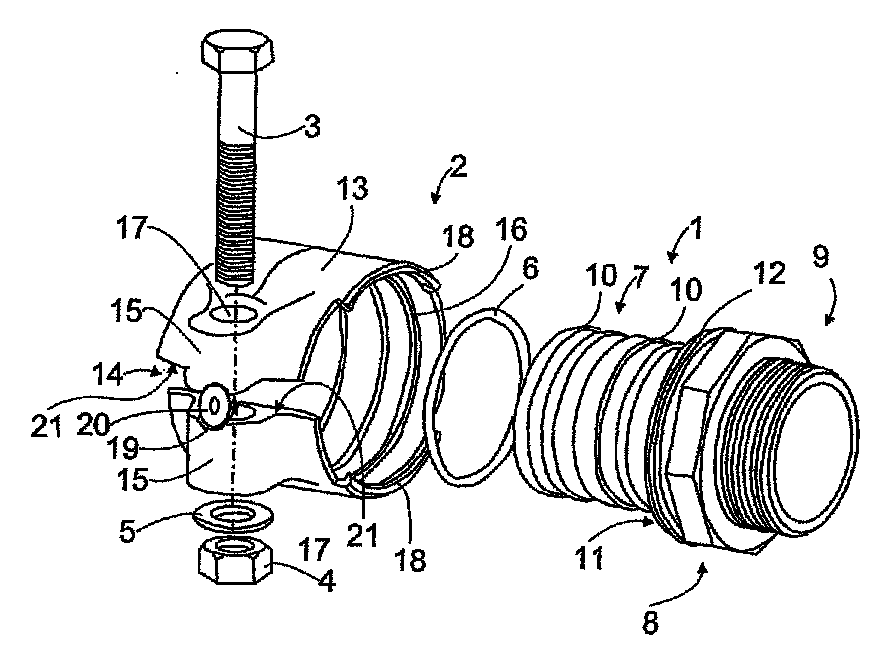
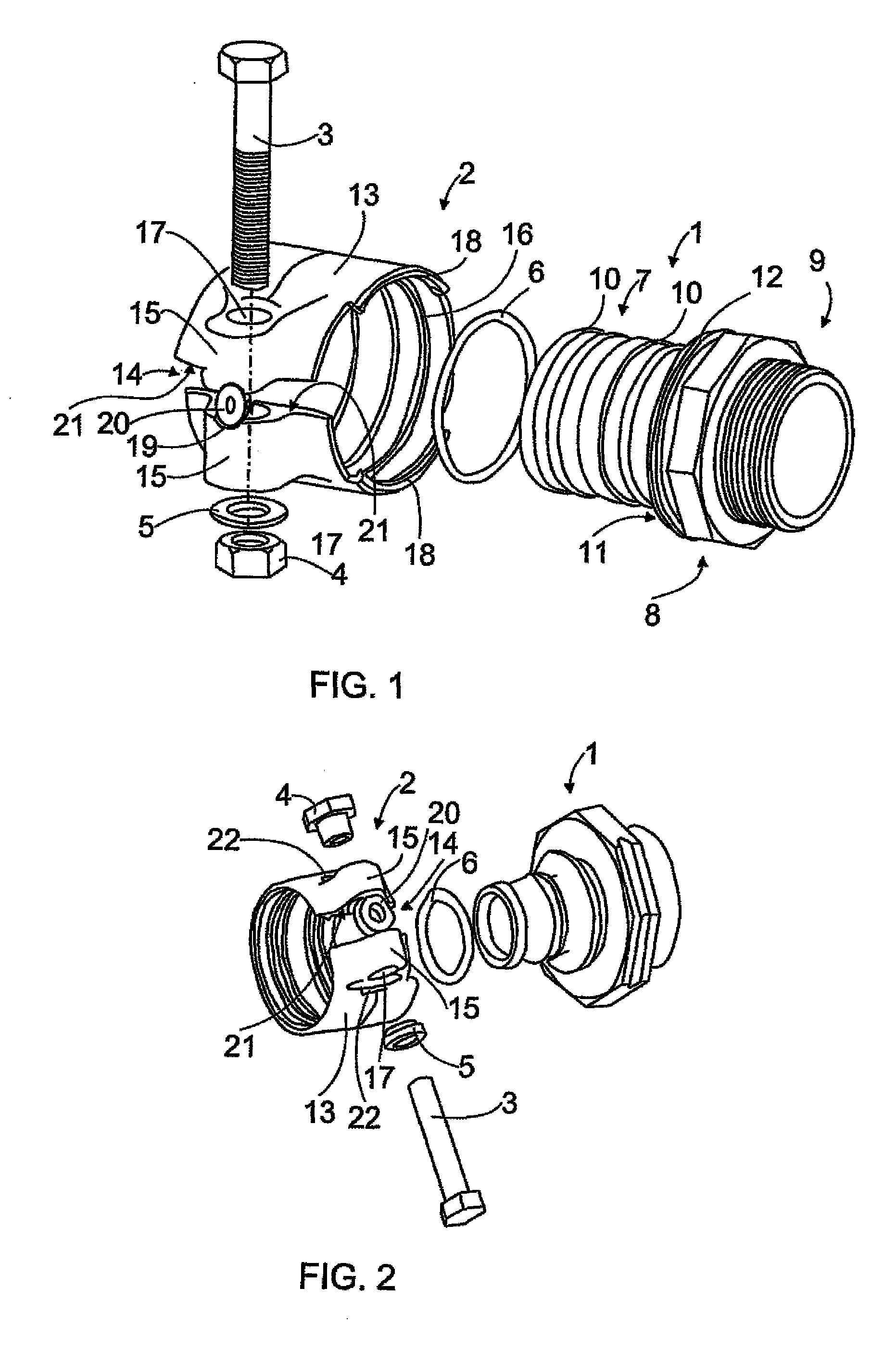
[0009]FIG. 1 illustrates the component parts of the coupling, these component parts including an inner sleeve 1, an outer sleeve 2, a bolt or a screw 3, a nut 4, a washer 5 and an O-ring 6.

[0010]The inner sleeve 1 is manufactured of a suitable material in the present context, preferably of a metallic material, although other materials may be suitable, such as various polymer materials, for instance. Particularly suitable inner sleeve materials are forged, sand-moulded and cast brass alloys.

[0011]The inner sleeve 1 is designed for connection to another coupling part and shall also provide an effective gripping and sealing function against the formable and ductile pipe wall and shall be capable of being locked to the outer sleeve. Accordingly, the inner sleeve includes a gripping and sealing part 7, a locking part 8, and a connecting part 9.

[0012]The gripping and sealing part of the inner sleeve, against which the ductile pipe wall is intended to abut, is provided with one or preferab...


PUM

PropertyMeasurementUnit
Diameteraaaaaaaaaa
Distanceaaaaaaaaaa
Surface areaaaaaaaaaaa

Abstract

The pipe coupling for connection to a pipe end of a pipe made of polymer material comprises an inner sleeve (1) which is intended for insertion into the pipe end and for abutment with the inner surface of said pipe end, an outer sleeve which is intended for abutment with the outer surface of said pipe end and which includes a slot-like opening (14), and means for adjusting said opening (14). The coupling further comprises a pre-widening means positioned between the edges (21) of the slot-like opening (14). The pre-widening means makes the slot-like opening (14) larger such that the inner diameter of the outer sleeve (2) is larger than the outer diameter of the pipe.

Description

BACKGROUND OF THE INVENTION[0001]The invention relates to a pipe coupling for connection to a pipe end of a pipe made of polymer material, comprising an inner sleeve which is intended for insertion into the pipe end and for abutment with the inner surface of said pipe end, an outer sleeve which is intended for abutment with the outer surface of said pipe end and which includes a slot-like opening, and means for adjusting said opening.[0002]A metal pipe coupling for interconnecting cross-linked polyethylene pipes installed in hot and cold water systems and in central and district heating pipe systems is known to the art from U.S. Pat. No. 4,039,212 and WO 00 / 01973. The coupling comprises an inner sleeve which is intended for insertion into the pipe and for abutment with the inner surface of said pipe end, an outer sleeve which is intended for abutment with the outer surface of said pipe end and which includes a slot-like opening, and means for adjusting said opening. When the couplin...

Claims


Application Information

Patent Timeline
IPC IPC(8): F16L55/00
CPCY10T24/1441F16L33/04
Inventor HAUKI, PETER J.LUNDEQUIST, YNGVE
Owner UPONOR INNOVATION AB
Why Eureka
Try Eureka