Winged electrode body for spinal cord stimulation

Active Publication Date: 2006-02-14
ADVANCED NEUROMODULATION SYST INC
View PDF10 Cites 194 Cited by
  • Summary
  • Abstract
  • Description
  • Claims
  • Application Information

AI Technical Summary

Benefits of technology

[0013]Accordingly, the present invention provides a unique implantable lead having a curved paddle. The paddle has an outer posterior curved surface to match the shape of the posterior portion of the epidural space and a flat inner or anterior surface to ensure that the maximum space within the epidural space is utilized, thereby preventing axial movement. Winged tips are added to further assist in preventing movement (such as axial or radial movement) within the epidural space and to more approximate the shape of the epidural space. A plurality of electrodes forms an array that transmits stimulation signals to surrounding spinal tissues. The array electrodes overlap in coverage for more complete stimulation of a targeted area. Further, this array can span distant nerve fibers or cover closely packed nerve fibers. Signals to the array can vary on an individual electrode lev

Problems solved by technology

However, because of present designs, electrical stimulation with a percutaneous lead occurs 360 degrees around the lead, thereby stimulating posterior portions of the epidural area as well the spinal area and hence, increases unnecessary power consumption.
Current lead designs suffer in that they often move axially, radially and/or longitudinally in the epidural space

Method used


Image

  • Winged electrode body for spinal cord stimulation
  • Winged electrode body for spinal cord stimulation
  • Winged electrode body for spinal cord stimulation

Examples


Example

[0022]Preferred embodiments of the present invention are illustrated in the figures, like numerals being used to refer to like and corresponding parts of the various drawings.

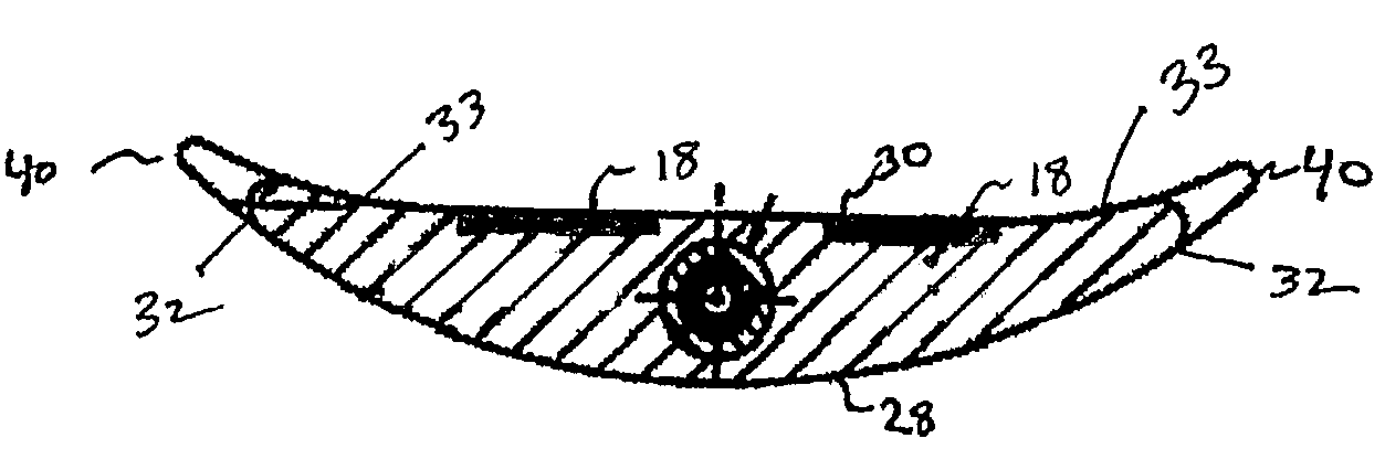
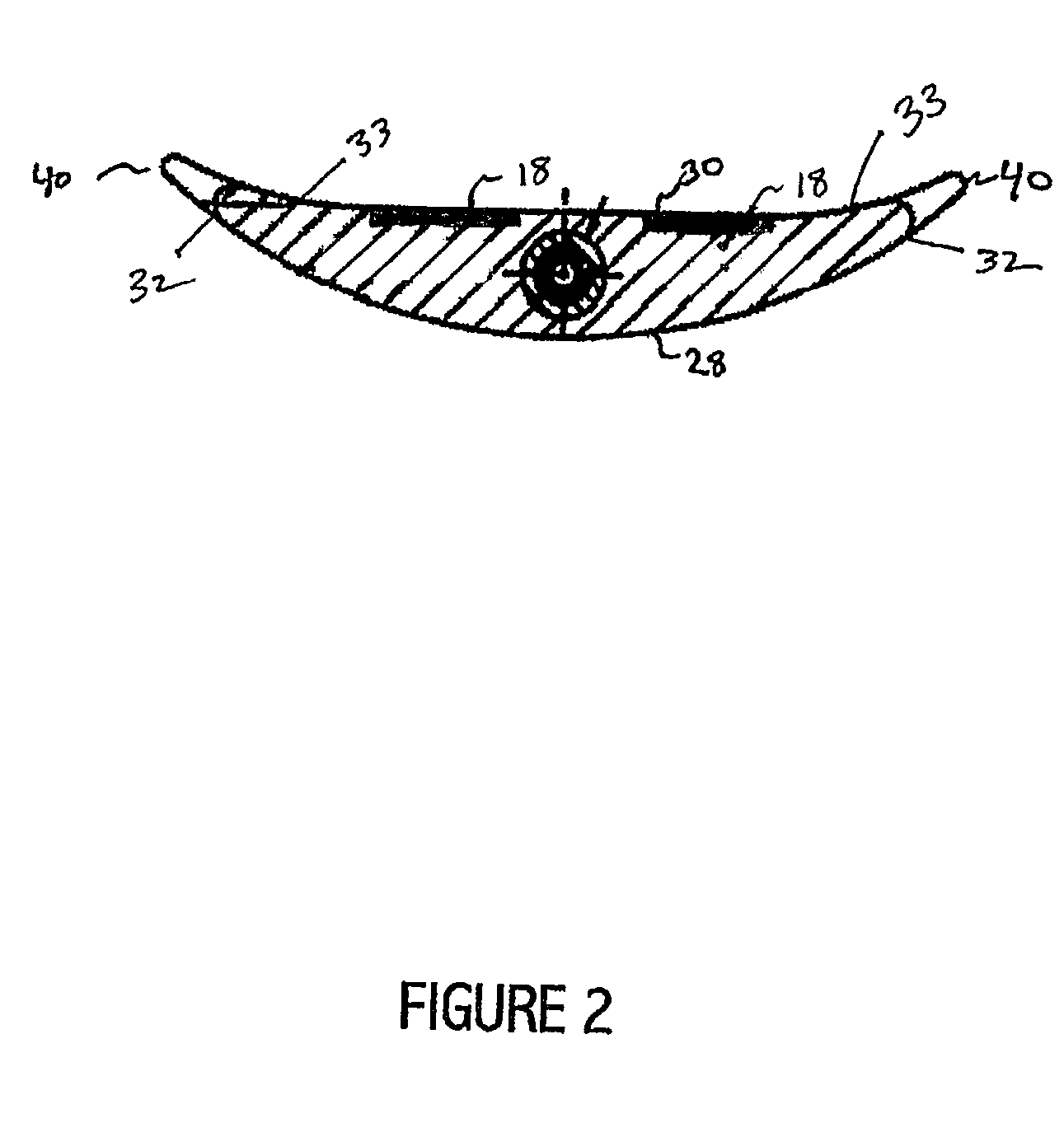
[0023]An implantable epidural lead for spinal cord stimulation is presented that includes a curved-back and winged-tipped paddle with a flat inner face having an array of electrodes coupled to conductors within a lead body. The conductors couple to a pulse generator or other stimulation device. The curved and winged paddle provides more complete electrical stimulation coverage to targeted human tissue by minimizing the potential gap between electrodes and targeted fibers.

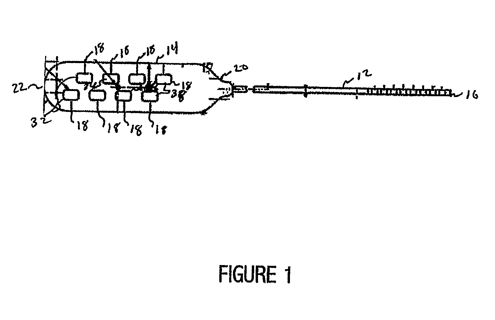
[0024]FIG. 1 provides an illustration of an epidural lead 10 for spinal cord stimulation comprises at least one lead body 12 and a paddle 14. Paddle 14 further comprises an array of electrodes 18 coupled at one end to lead body 12. Lead body 12 further comprises a number of wire conductors. The actual number of wire conductors depends on the nu...


PUM


Abstract

An implantable stimulation system including epidural lead for spinal cord stimulation that includes a paddle having a curved proximal end and lateral winged tips and an array of electrodes coupled to conductors within a lead body. The conductors couple to a pulse generator or other stimulation device. The curved and winged paddle provides more complete electrical stimulation coverage to targeted human tissue by minimizing the potential gap between electrodes and targeted fibers.

Description

TECHNICAL FIELD OF THE INVENTION[0001]The present invention relates generally to implantable medical stimulators and more particularly to an epidural lead having a plurality of electrodes wherein the lead is shaped to optimize electrical coupling between the electrodes and the spinal cord.BACKGROUND OF THE INVENTION[0002]Electrical stimulation of the spinal cord or peripheral nerves can result in pain reduction and / or elimination. Medical leads having electrodes are often implanted near the spinal column to provide pain relief for chronic intractable pain. The electrodes stimulate tissue within the spinal column to reduce pain sensations at other parts of the body. The stimulation signals applied can be optimized for pain reduction or elimination depending on the location of the pain.[0003]The area of excitation and the intensity of excitation vary according to the stimulation signals. To vary the area of excitation, an array of electrodes implanted near nerve tissue can be configur...

Claims


Application Information

Patent Timeline
IPC IPC(8): A61N1/00A61N1/05
CPCA61N1/0553
Inventor JORDAN, RICHARD
Owner ADVANCED NEUROMODULATION SYST INC
Why Eureka
Try Eureka