
Dynamic vibration attenuation boring tool

A technology of dynamic vibration reduction and boring tools, which is applied to the accessories of tool holders, tools for lathes, turning equipment, etc., which can solve the problems of low stiffness of gear levers, inability to differentiate vibration reduction, and affect processing quality, etc., to prevent Axial movement, good vibration damping effect, and simple structure

Inactive Publication Date: 2017-02-01
SOUTHEAST UNIV
View PDF7 Cites 15 Cited by
  • Summary
  • Abstract
  • Description
  • Claims
  • Application Information

AI Technical Summary

Problems solved by technology

Especially when the gear rod has a large length-to-diameter ratio, the gear rod has low stiffness and severe vibration, so that the roughness of the processed surface cannot meet the requirements, which affects the processing quality of the hole
Most of the current dynamic vibration reduction methods are to add an equal-diameter vibration core in the body of the boring bar for dynamic vibration reduction. Such a vibration reduction method can only reduce the vibration at a certain fixed position of the tool bar. During cutting, since the boring tool is a cantilever structure, the closer to the tool head, the greater the vibration amplitude, and the greater the mass of the vibration core is required for dynamic vibration reduction. The current vibration reduction method cannot account for the different vibration amplitudes at different positions of the tool bar. differentiated vibration reduction

Method used


Image

  • Dynamic vibration attenuation boring tool
  • Dynamic vibration attenuation boring tool

Examples


Embodiment Construction

[0015] The present invention will be further described below in conjunction with the accompanying drawings.

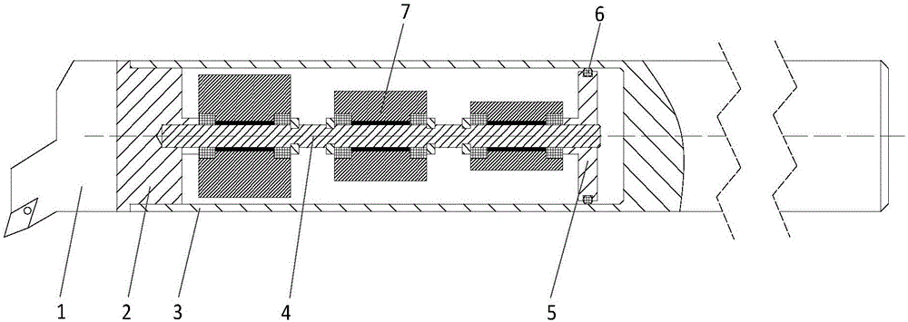
[0016] Such as figure 1 As shown, a power damping boring tool of the present invention includes a cutter head 1, a cutter head end cover 2, a cutter bar 3, a connecting rod 4 and a cutter tail end cover 5, and the connecting rod 4 is arranged in the cutter bar 3, The two ends of the connecting rod 4 are respectively connected with the cutter head end cover 2 and the cutter tail end cover 5, and the cutter head end cover 2 is connected with the cutter bar 3 at the same time. The inner walls of the rod 3 are connected by an O-ring 6 , and at least two damping modules 7 are arranged on the connecting rod 4 .

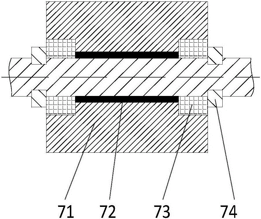
[0017] The structure of the damping module 7 is as figure 2 As shown, it includes vibrating core 71, damping oil 72 and rubber ring 73. The vibrating core is suspended on the connecting rod 4 through the rubber ring 73. The space between the vibrating core 71 and...


PUM


Abstract

The invention discloses a dynamic vibration attenuation boring tool which comprises a tool bit, a tool bar, a tool bit end cover, a connection rod and a tool tail end cover, wherein the connection rod is arranged in the tool bar; two ends of the connection rod are respectively connected with the tool bit end cover and the tool tail end cover; the tool bit end cover is also connected with the tool bar; the tool bit is arranged on the tool bit end cover; the tool tail end cover is connected with the inner wall of the tool bar through an O-shaped ring; at least two vibration attenuation modules are arranged on the connection rod, and are axially fixed on the connection rod through clamping springs; the vibration attenuation modules comprise vibration cores, damping oil and rubber rings; the vibration cores are suspended on the connection rod through the rubber rings; and the damping oil is filled between the vibration cores and the connection rod. According to the dynamic vibration attenuation boring tool, the diameters of the vibration cores of different vibration attenuation modules are different, so that differentiated vibration attenuation can be performed on different positions of the tool bar, vibration generated during part machining can be attenuated, and the quality of a machined surface is improved.

Description

technical field [0001] The invention relates to a cutting tool, in particular to a dynamic damping boring tool for hole processing, and belongs to the technical field of metal cutting. Background technique [0002] In machining, hole machining is usually performed by boring tools. During machining, the boring tool and the workpiece periodically cut in and out, causing the boring bar to vibrate. Especially when the gear rod has a large length-diameter ratio, the gear rod has low stiffness and severe vibration, so that the roughness of the processed surface cannot meet the requirements, which affects the processing quality of the hole. Most of the current dynamic vibration reduction methods are to add an equal-diameter vibration core in the body of the boring bar for dynamic vibration reduction. Such a vibration reduction method can only reduce the vibration at a certain fixed position of the tool bar. During cutting, since the boring tool is a cantilever structure, the clos...

Claims


Application Information

Patent Timeline
Patent Type & Authority Applications(China)
IPC IPC(8): B23B27/00
CPCB23B27/002
Inventor 孙蓓蓓李烈何苗华海涛陈建栋薛飞焦仁强
Owner SOUTHEAST UNIV
Learn More