Fluid-filled type engine mount

a technology of engine mount and filling, which is applied in the direction of shock absorbers, machine supports, transportation and packaging, etc., can solve the problems of abnormal noise or vibration emitted by the mount, and abnormal noise or shock on a level that can be felt by passengers, etc., to achieve the effect of simplifying the structure of affixing the partition member to the second mounting member, high efficiency of space use, and compact structur

Active Publication Date: 2007-01-18
SUMITOMO RIKO CO LTD
View PDF6 Cites 21 Cited by
  • Summary
  • Abstract
  • Description
  • Claims
  • Application Information

AI Technical Summary

Benefits of technology

[0041] In this mode, the structure for affixing the partition member to the second mounting member is simplified, and the pressure-receiving chamber and equilibrium chamber are produced with a minimum of parts and with highly efficient use of space, providing an advantage in terms of making the mount more compact.
[0042] As will be apparent from the preceding description, in the fluid-filled type engine mount constructed in accordance with the present invention, the presence of the movable film endowed with non-linear spring properties makes it possible assure an adequate level of vibration damping action on the basis of flow action of fluids through the first and second orifice passages. At the same time, the hard spring properties of the non-linear spring zone of the movable film makes it possible to reduce or avoid conditions of high negative pressure thought to be responsible for the formation of cavitation bubbles. As a result, formation and bursting of bubbles can be suppressed, and the problem of impulsive abnormal noise and vibration can be suppressed effectively.

Problems solved by technology

These engine mounts however have been suffer from a problem that when large vibrations are input across the first mounting member and the second mounting members, in some instances abnormal noise or vibration may be emitted by the mount.
An investigation conducted by the inventors has shown that, in an automobile equipped with a fluid-filled type engine mount of conventional construction, abnormal noise or shock on a level that can be felt by passengers is sometimes produced in the cabin when the vehicle drives over deep corrugated pavement.

Method used


Image

  • Fluid-filled type engine mount
  • Fluid-filled type engine mount
  • Fluid-filled type engine mount

Examples


first embodiment

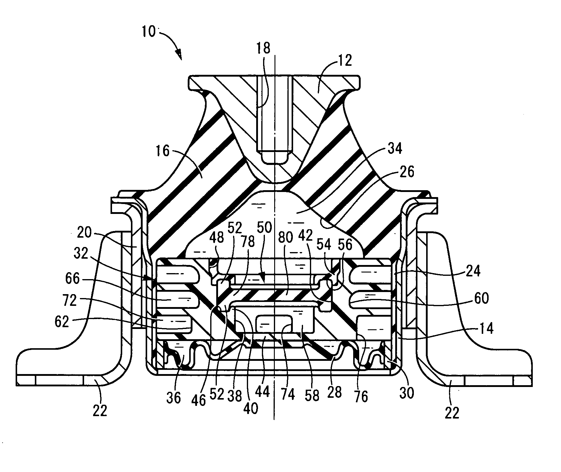
[0052] Referring first to FIG. 1, there is shown a fluid-filled type engine mount in the form of an automotive engine mount 10 of construction according to the invention. This engine mount 10 is of construction wherein a first mounting member 12 of metal and a second mounting member 14 of metal are elastically coupled by a main rubber elastic body 16. The engine mount 10 is installed in an automotive vehicle by mounting the first mounting member 12 to the power unit of the vehicle as an one of the two components connected together in a vibration damping fashion, and mounting the second mounting member 14 to the vehicle body as the other of the two components connected together in a vibration damping fashion, so that the power unit is supported on the vehicle body in a vibration damping fashion. In the installed state, the distributed load of the power unit is exerted on the mount 10, the first mounting member 12 and the second mounting member 14 undergo displacement towards one anot...

second embodiment

[0082] In the rubber elastic plate 82 pertaining to the second embodiment, the thickness dimension decreases gradually going diametrically inward from the outside edge portion of the rubber elastic plate 82 where the annular projections 52, 52 are formed. In particularly, with regard to the extent to which the thickness dimension of the rubber elastic plate 82 decreases, the decrease is greater in the generally annular disk shaped diametrically medial portion of the rubber elastic plate 82 reaching from its outside edge portion to the center portion than in the generally disk-shaped center portion of the rubber elastic plate 82. The diametrically medial portion in which the extent to which the thickness dimension decreases is greater constitutes a thick portion 84, while the center portion in which the extent to which the thickness dimension decreases is smaller such that the thickness dimension is approximately constant constitutes a thin portion 86.

[0083] When idling vibration is ...

third embodiment

[0084] In the rubber elastic plate 88 pertaining to the third embodiment, a disk-shaped portion 90 of generally circular disk shape is formed in the center portion. At the outside peripheral side of the disk-shaped portion 90, between the disk-shaped portion 90 and the outside peripheral edge portion thereof where the annular projection 52 is integrally formed, there is formed a tapered portion 92 of tapering shape whose diameter dimension decreases gradually from the intermediate chamber 58 towards the pressure-receiving chamber 34, with the tapered portion 92 projecting from the intermediate chamber 58 towards the pressure-receiving chamber 34.

[0085] When idling vibration is input, deformation of the rubber elastic plate 88 is produced in the low deflection zone by means of deformation of the disk-shaped portion 90. Whereas when vibration of amplitude greater than idling vibration in a frequency range higher than the resonance frequency of the first orifice passage 66 is input, th...


PUM


Abstract

A fluid-filled type engine mount having a pressure receiving chamber and an equilibrium chamber connected together through a first orifice passage, and an intermediate chamber connected to the equilibrium chamber through a second orifice passage. The intermediate chamber is partially defined by a movable film, and the pressure-receiving chamber and the intermediate chamber are situated to either side of the movable film. The movable film is a tabular rubber elastic body, and is imparted with non-linear spring properties in response to elastic deformation in a width direction thereof so that its deformation during input of idling vibration occurs in a low spring properties zone, whereas its deformation during input of vibration of greater amplitude than the idling vibration in a higher frequency range than a resonance frequency of the first orifice passage reaches a high spring properties zone.

Description

INCORPORATED BY REFERENCE [0001] The disclosure of Japanese Patent Application No. 2005-206015 filed on Jul. 14, 2005 and No. 2006-169028 filed on Jun. 19, 2006, each including the specification, drawings and abstract is incorporated herein by reference in its entirety. BACKGROUND OF THE INVENTION [0002] 1. Field of the Invention [0003] The present invention relates to a fluid-filled type engine mount designed to exhibit vibration damping action based on the flow action of a non-compressible fluid sealed therein, and more particularly to a fluid-filled type engine mount of novel construction furnished with a first orifice passage and a second orifice passage tuned to a higher frequency band than the first orifice passage, and able to produce vibration damping action against vibration in a multiplicity of wide frequency ranges. [0004] 2. Description of the Related Art [0005] Engine mounts are known as components to be installed between a vehicle body and a power unit that includes an...

Claims


Application Information

Patent Timeline
Patent Type & Authority Applications(United States)
IPC IPC(8): F16F13/00
CPCF16F13/106
Inventor KATAGIRI, AKIRASUZUKI, TATSUYAHAMADA, MASAAKI
Owner SUMITOMO RIKO CO LTD
Why Eureka
Try Eureka