Modular static intervertebral trial

a technology of intervertebral and trial, applied in the field of modular static intervertebral trial, can solve the problems of increasing the difficulty of selecting the appropriate size of the implant, and achieve the effects of reducing the number of trial iterations, reducing the risk to the patient, and reducing the total number of components

Active Publication Date: 2009-02-10
DEPUY SPINE INC (US)
View PDF10 Cites 39 Cited by
  • Summary
  • Abstract
  • Description
  • Claims
  • Application Information

AI Technical Summary

Benefits of technology

[0009]Utilizing this kit can significantly reduce the number of trialing iterations required to determine the appropriately sized implant, as well as reduce the procedure time and, consequently, risk to the patient, and reduces the total number of components in the kit, more efficiently utilizing space within the constraints of the operating room.

Problems solved by technology

While these sizing options enable the surgeon to better accommodate the patient population, selecting the appropriately sized implant becomes increasingly difficult.

Method used


Image

  • Modular static intervertebral trial
  • Modular static intervertebral trial
  • Modular static intervertebral trial

Examples


Embodiment Construction

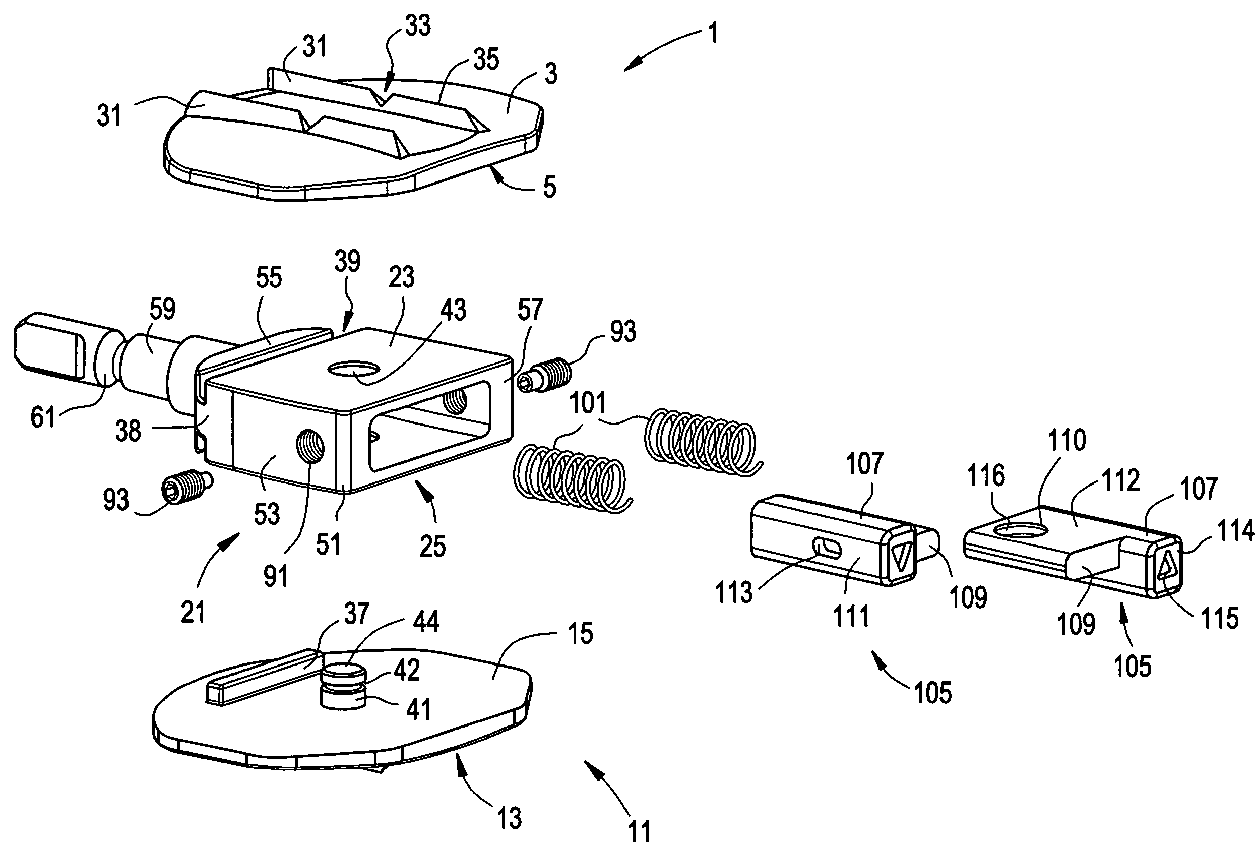
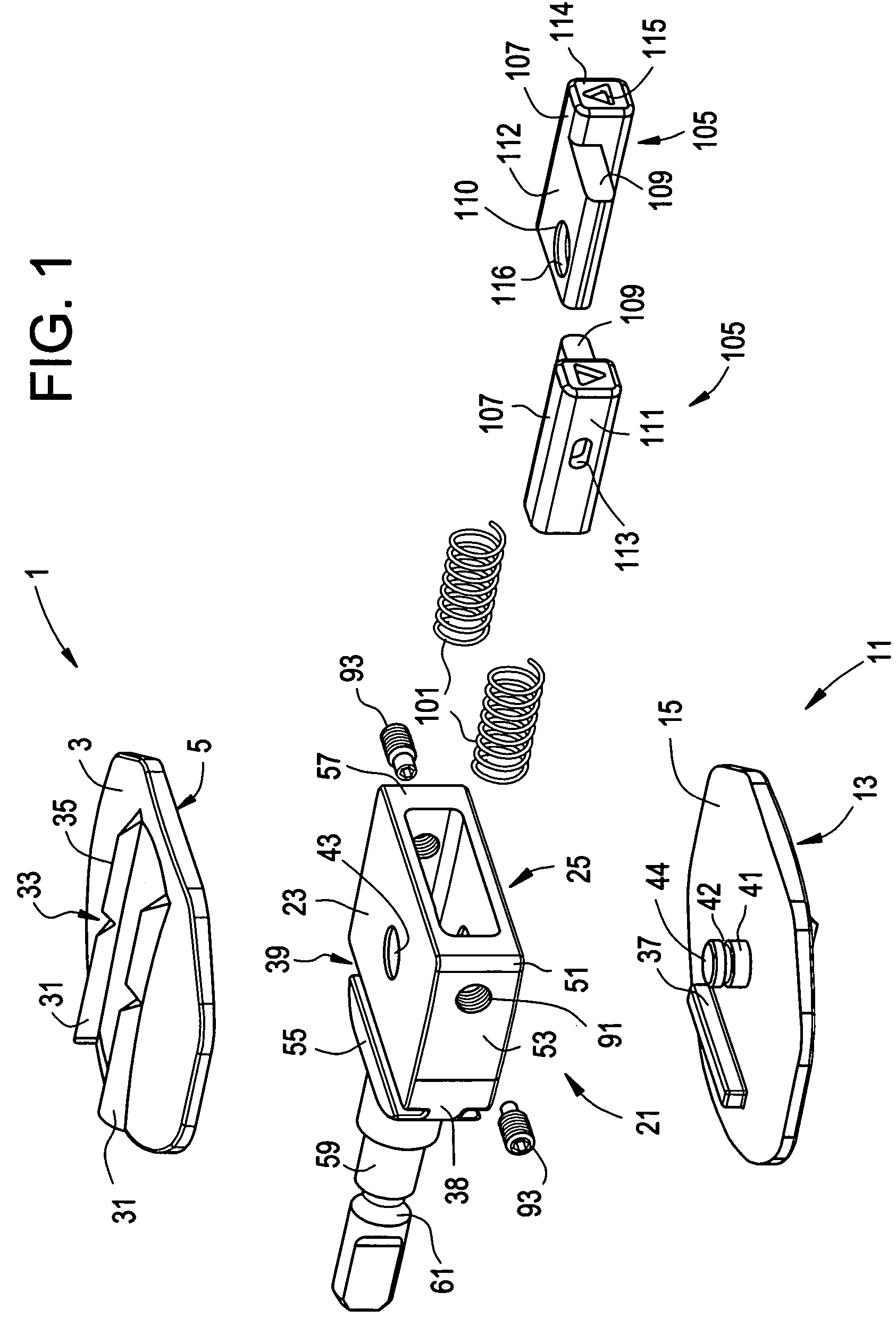
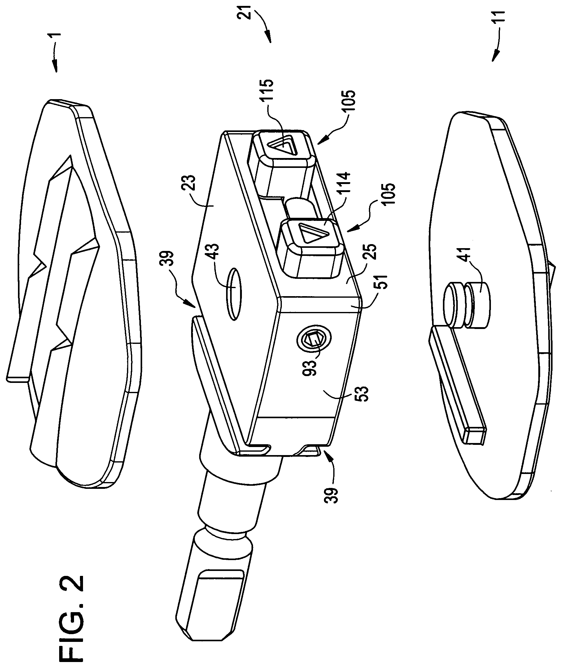
[0013]Now referring to FIG. 1, there is provided an exploded version of the modular static trial of the present invention. In particular, there is provided a modular intervertebral trial, comprising:[0014]a) an upper trial vertebral endplate 1 comprising:[0015]i) an outer surface 3 adapted to mate with a first vertebral body,[0016]ii) an inner surface 5,[0017]b) a lower trial vertebral endplate 11 comprising:[0018]i) an outer surface 13 adapted to mate with a second vertebral body, and[0019]ii) an inner surface 15[0020]c) a base member 21 comprising:[0021]i) an upper surface 23 removably attached to the inner surface of the upper endplate, and[0022]ii) a lower surface 25 removably attached to the inner surface of the lower endplate.

[0023]In preferred embodiments, the outer surface of each endplate has a pair of parallel tracks 31 extending outwardly therefrom, wherein the tracks run in the anterior-posterior direction. These tracks are centered about the midline of the trial and are...


PUM


Abstract

A modular, static intervertebral trial having interchangeable base members having different heights, and interchangeable endplates having different footprints and angles.

Description

BACKGROUND OF THE INVENTION[0001]The leading cause of lower back pain arises from rupture or degeneration of lumbar intervertebral discs. Pain in the lower extremities is caused by the compression of spinal nerve roots by a bulging disc, while lower back pain is caused by collapse of the disc and by the adverse effects of articulation weight through a damaged, unstable vertebral joint. One proposed method of managing these problems is to remove the problematic disc and replace it with a prosthetic disc that allows for the natural motion between the adjacent vertebrae (“a motion disc”).[0002]Prior to inserting the disc, however, the surgeon typically desires to insure that the properly sized implant has been identified for the particular patient. To this end, trial implants are commonly included within the instrument sets that allow the surgeon to temporarily insert the trial into the intervertebral disc space and assess whether the height and footprint of the trial would be appropri...

Claims


Application Information

Patent Timeline
Patent Type & Authority Patents(United States)
IPC IPC(8): A61F2/44
CPCA61F2/4684A61F2/44A61F2002/3008A61F2002/30383A61F2002/30535A61F2002/30566A61F2002/30604A61F2002/30616A61F2002/3071A61F2002/30884A61F2220/0025A61F2250/0058A61F2250/0085A61F2250/0098
Inventor STAD, SHAWN
Owner DEPUY SPINE INC (US)
Why Eureka
Try Eureka