Fluid-filled active vibration-damping device

a technology of active vibration and damping device, which is applied in the direction of shock absorbers, machine supports, mechanical equipment, etc., can solve the problems of reducing the flow volume through the orifice passage, affecting the excitation displacement of the excitation member by the actuator, and deteriorating vibration damping performance, so as to facilitate the restraint increase the excitation amplitude of the excitation member. , the effect of active vibration damping

Inactive Publication Date: 2013-01-03
SUMITOMO RIKO CO LTD
View PDF5 Cites 21 Cited by
  • Summary
  • Abstract
  • Description
  • Claims
  • Application Information

AI Technical Summary

Benefits of technology

[0023]With the fourth mode, a fluid flow through the through hole between the pressure receiving fluid chamber and the excitation fluid chamber is maintained up to the frequency range at which the filter orifice is substantially blocked by anti-resonance, so an active vibration damping effect is more advantageously exhibited.
[0024]With the present invention, by forming the through hole piercing in the thickness direction of the movable membrane, when the excitation member is excited by the actuator, in addition to deformation of the movable membrane, fluid flow also occurs between the pressure receiving fluid chamber and the excitation fluid chamber through the through hole. This makes it possible to ease the restraint of the excitation member by the action of the fluid pressure of the excitation fluid chamber. Therefore, it is possible to make the excitation amplitude of the excitation member larger, and to effectively obtain the target active vibration damping effect. In addition, when a large amplitude vibration is input, with restriction of the movable membrane deformation by the holding space wall part, fluid flow volume through the orifice passage is ensured, and a passive vibration damping effect is exhibited based on the fluid flow action.

Problems solved by technology

As a result, the fluid flow volume through the orifice passage decreases, leading to a problem of deterioration of vibration damping performance.
However, with the switching mechanism using the movable plate like that disclosed in JP-A-2009-92235, when a rigid movable plate is held in contact with the top and bottom wall parts of the holding space due to large amplitude vibration input and the excitation fluid chamber is sealed, there is the risk that the excitation displacement of the excitation member by the actuator will be hindered by the fluid pressure of the excitation fluid chamber or the like.

Method used


Image

  • Fluid-filled active vibration-damping device
  • Fluid-filled active vibration-damping device
  • Fluid-filled active vibration-damping device

Examples


Embodiment Construction

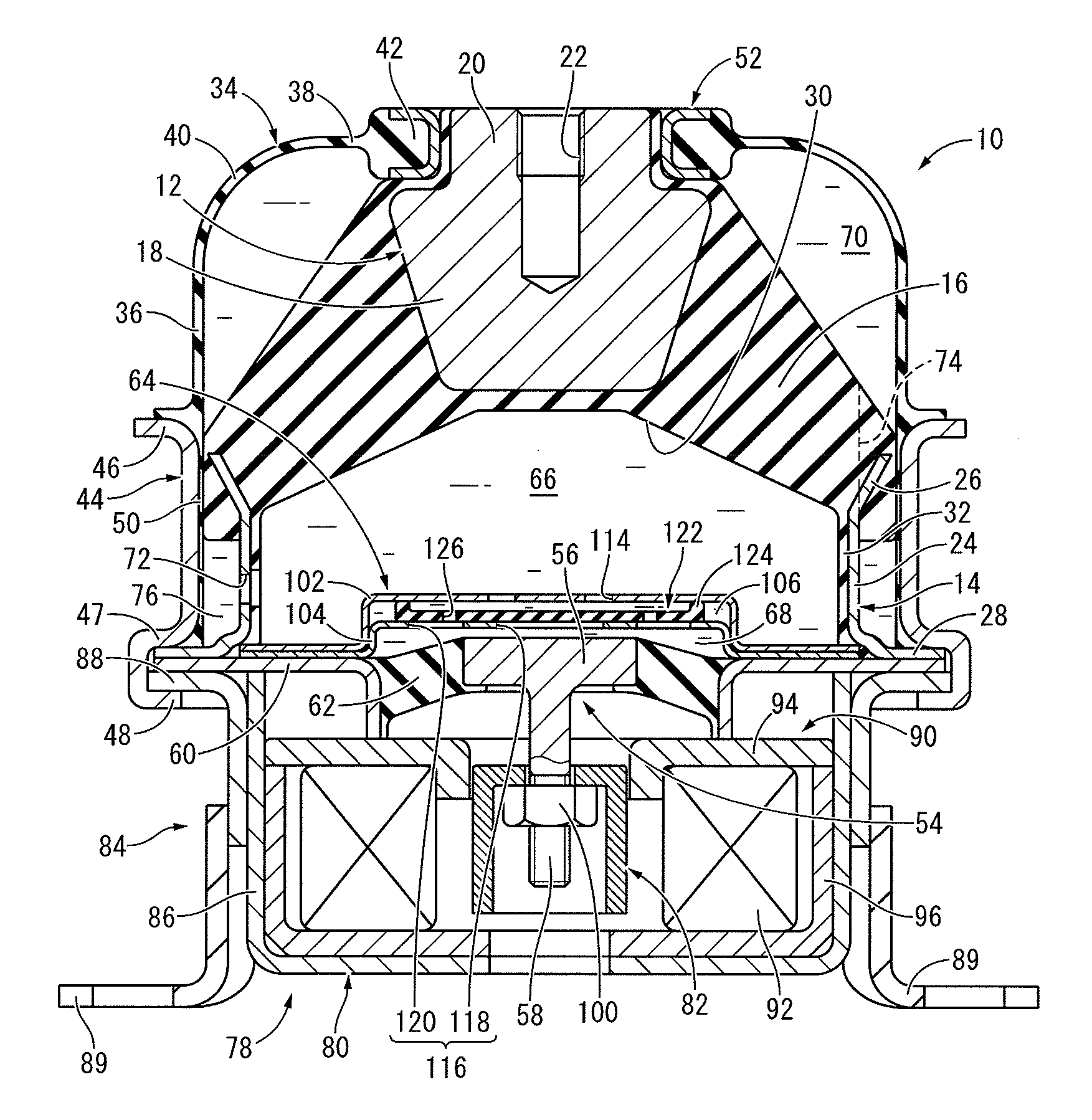
[0032]FIG. 1 shows an automobile engine mount 10 as the first embodiment of the fluid-filled active vibration damping device constituted according to the present invention. The engine mount 10 has a constitution for which a first mounting member 12 and a second mounting member 14 are elastically connected by a main rubber elastic body 16, and the first mounting member 12 is attached to a power unit (not shown), and the second mounting member 14 attached to a vehicle body (not shown). With the description below, the up-down direction means the up-down direction in FIG. 1 as a rule.

[0033]More specifically, the first mounting member 12 exhibits overall a small diameter, roughly stepped round column shape, and is equipped with a lower fixing part 18 having a reverse direction, roughly truncated cone shape and a round column shaped upper engaging part 20 projecting facing upward with a smaller diameter than the top end part of the lower fixing part 18 as an integrated unit. Furthermore, ...


PUM


Abstract

A fluid-filled active vibration damping device including a partition member having a holding space formed therein and a movable membrane installed in the holding space. A filter orifice tuned to a higher frequency than an orifice passage is formed at one wall part of the holding space facing to one surface of the movable membrane, and the holding space is in communication with one of a pressure receiving fluid chamber and an excitation fluid chamber through the filter orifice. An open hole is formed on the other wall part of the holding space facing to the other surface of the movable membrane opposite to the one surface in the thickness direction, and the holding space is in communication with the other of the two fluid chambers through the open hole. A through hole pierces the movable membrane in the thickness direction.

Description

INCORPORATED BY REFERENCE[0001]The disclosure of Japanese Patent Application No. 2011-145052 filed on Jun. 30, 2011 including the specification, drawings and abstract is incorporated herein by reference in its entirety.BACKGROUND OF THE INVENTION[0002]1. Field of the Invention[0003]The present invention relates to a fluid-filled vibration damping device used for an automobile engine mount or the like, for example, and particularly relates to a fluid-filled active vibration damping device made to exhibit an active vibration damping effect based on excitation force applied from outside.[0004]2. Description of the Related Art[0005]As one type of vibration damping devices applied for the engine mount of automobiles or the like, for example, fluid-filled vibration damping devices which use the flow action of the fluid enclosed in the interior are known. This fluid-filled vibration damping device has a first mounting member and a second mounting member elastically connected by a main rubb...

Claims


Application Information

Patent Timeline
Patent Type & Authority Applications(United States)
IPC IPC(8): F16F13/26F16F13/08
CPCF16F13/106F16F13/26
Inventor KANAYA, TOMOHIRO
Owner SUMITOMO RIKO CO LTD
Why Eureka
Try Eureka