Capacitively coupled remote plasma source with large operating pressure range

a plasma source and remote technology, applied in the direction of electrical equipment, basic electric elements, electric discharge tubes, etc., can solve the problems of large magnetic field, large system cost, and high cost of microwave delivery systems, so as to increase the system mtbf (mean time between failures) and reduce system cost. , the effect of increasing the system cos

Inactive Publication Date: 2010-04-29
JI HELIN
View PDF13 Cites 203 Cited by
  • Summary
  • Abstract
  • Description
  • Claims
  • Application Information

AI Technical Summary

Benefits of technology

[0015]It is another objective to provide one remote plasma source without complicated RF matching network. Such matching network often adds up system cost and increases the system MTBF (mean time between failures). This can be achieved in several ways: 1) pre-tuned coaxial structure as in U.S. Pat. No. 5,656,123; 2) a conventional L-match pre-tuned and fixed to allow a partial match with no plasma to achieve plasma strike; or 3) an autotransformer self-resonant structure, again pre-tuned to allow strike. It shall be pointed out that such remote plasma source with impedance matching network is also covered by this invention.
[0016]One advantage of this apparatus is that the plasma in this system can self strike. This further reduces the system cost and makes the source easy to use and operate.
[0017]The direct guiding of the plasma out of metal electrode allows flexible design in radical distributing pattern for selective area applications like wafer edge or materials walls.

Problems solved by technology

Such a high potential is good for highly anisotropic etching or deposition but it may cause damage to the structure on the wafer surface in certain application such as interlayer dielectric etching especially low-k oxide layer etching in sub-100 nm VLSI manufacturing.
The limit of this type of plasma source is that the plasma density falls rapidly from the coupling coils because the magnetic field intensity decreases with increasing distances from coils.
However this type of sources requires large magnetic field and an expensive microwave delivery system.
This type of source still needs special plasma ignition mechanism and it lacks flexibilities in selective surface plasma processing.
Ion shower grid type plasma process (U.S. Pat. Nos. 7,291,360 and 7,244,474, both to Hanawa et al.) is used to generate flux of ions from plasma so it is not suitable for sensitive materials surface treatment such as low-k dielectric layer etching.

Method used


Image

  • Capacitively coupled remote plasma source with large operating pressure range
  • Capacitively coupled remote plasma source with large operating pressure range
  • Capacitively coupled remote plasma source with large operating pressure range

Examples


Embodiment Construction

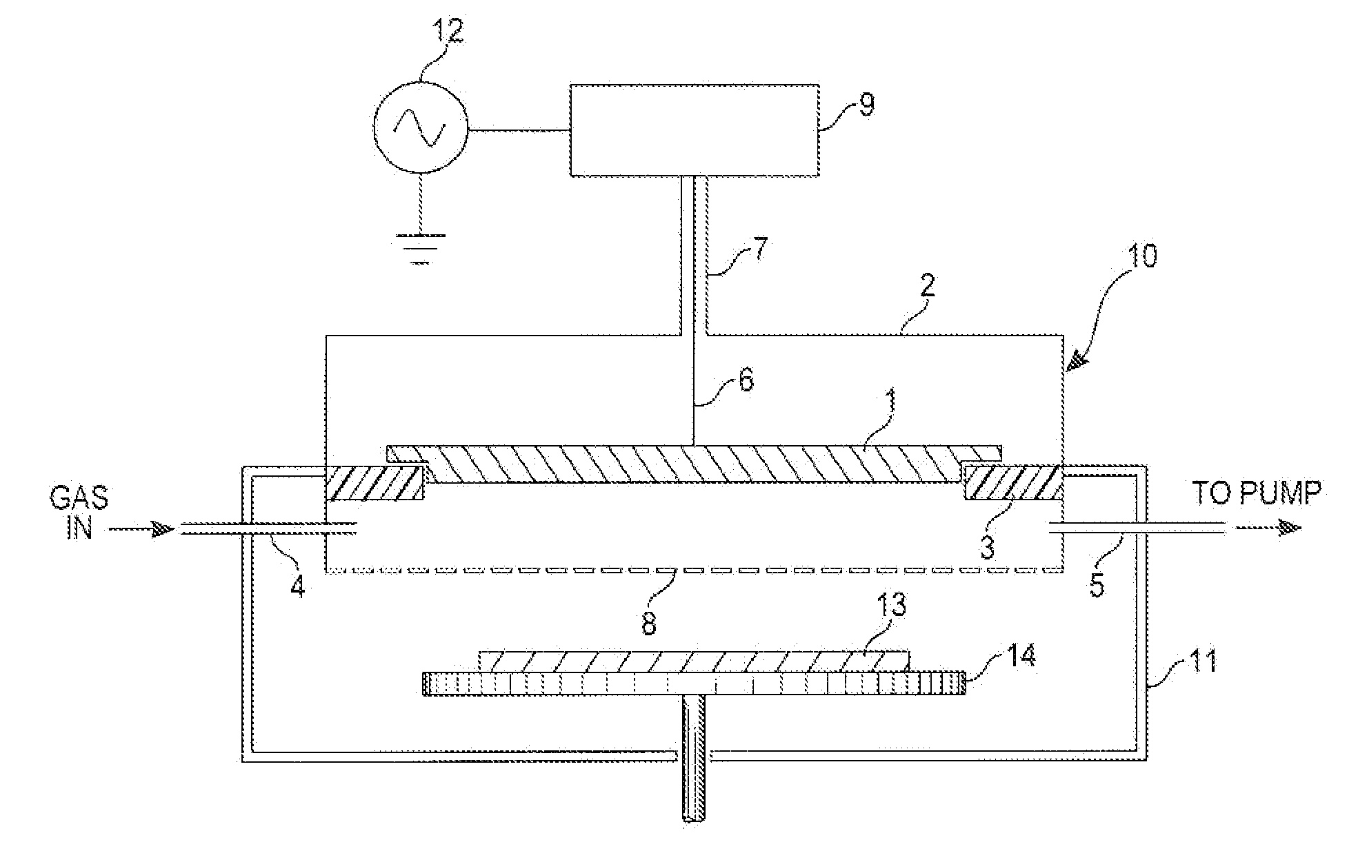
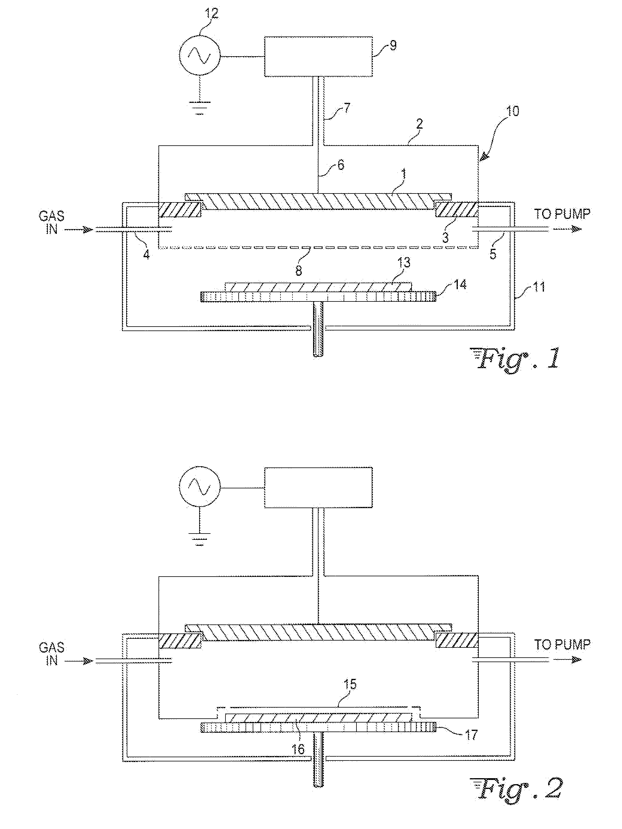
[0021]With reference to FIG. 1, a remote plasma source 10 is driven by RF source 12 and integrated into a process chamber such as a semiconductor wafer-processing chamber. RF VHF source 12 is connected to the RF matchbox 9. The plasma entering the machine chamber from remote source 10 will react with materials 13 on pedestal 14.

[0022]The inner conductor 6 of coax cable from match box 9 is connected to one electrode 1. The outer conductor 7 of the coaxial cable forms one enclosure 2 around inner electrode 1, and they are insulated with dielectric ring 3. Enclosure 2 is situated on chamber 11. The enclosure 2 is connected to the output of one RF matchbox and the RF generator is connected to input of the matchbox. The internal elements are tuned to partially match to strike, yet provide a decent match when plasma is on.

[0023]The additional pump port 5 is to help maintain the vacuum level in the remote source lower than the vacuum level in the machine chamber, into which the remote plas...


PUM

PropertyMeasurementUnit
frequencyaaaaaaaaaa
diameteraaaaaaaaaa
densityaaaaaaaaaa

Abstract

A radio frequency (RF) coaxial resonator feeding a saltshaker-like gas distributing electrode assembly forms a capacitively coupled plasma source. This apparatus can generate plasma of high density over a wide pressure range and large process window. The system may be used as a remote radical-rich plasma source for materials surface processing.

Description

CROSS-REFERENCE TO RELATED APPLICATION[0001]This application claims priority under 35 U.S.C. 119(e) from U.S. provisional application 61 / 108,809 filed Oct. 27, 2008.TECHNICAL FIELD[0002]The present invention relates generally to apparatus and methods for producing remotely radical-rich plasma for surface treatment including those of semiconductor devices, flat panel displays, thin film solar panels and polymers.BACKGROUND ART[0003]Plasma containing reactive ions and free radicals has been widely used in material processing such as semiconductor wafers, flat panel displays and powders. In particular, the plasma generation is indispensable to the semiconductor manufacturing industry, including etching, photoresist stripping, Physical Vapor Deposition (PVD) and Plasma Enhanced Chemical Vapor Deposition (PECVD). Several methods have been proposed to generate plasma for these applications.[0004]The most common one is the capacitive radio frequency (RF) discharge at the frequency of 13.56...

Claims


Application Information

Patent Timeline
Patent Type & Authority Applications(United States)
IPC IPC(8): H01L21/3065
CPCH01J37/32357H01J37/32532H01J37/32422
Inventor JI, HELIN
Owner JI HELIN
Why Eureka
Try Eureka