Controlling Movement of a Solar Energy Member

a solar energy and solar energy technology, applied in the direction of solar heat collectors, lighting and heating equipment, instruments, etc., can solve the problems of high reduction ratio of gearboxes, unstable operation platform and/or structure, and high cost of gearboxes

Inactive Publication Date: 2012-07-12
GOOGLE LLC
View PDF0 Cites 24 Cited by
  • Summary
  • Abstract
  • Description
  • Claims
  • Application Information

AI Technical Summary

Benefits of technology

[0008]In another general embodiment, a method for controlling a solar energy system including a solar energy member, a vertical support post, and a damper assembly, includes: determining, with a controller, to move a solar energy member from a first position to a second position different than the first position; operating an actuator assembly to apply a substantially static torque to the solar energy member to move the solar energy member to the second position; ...

Problems solved by technology

Substantial wind forces on a planar object, such as a heliostat, may apply forces and torques which tend to knock the beam off-target.
Heliostats, however, may require a stable operational platform and/or structure even when acted-upon by external forces, especially wind.
These requirements are often ...

Method used


Image

  • Controlling Movement of a Solar Energy Member
  • Controlling Movement of a Solar Energy Member
  • Controlling Movement of a Solar Energy Member

Examples


Embodiment Construction

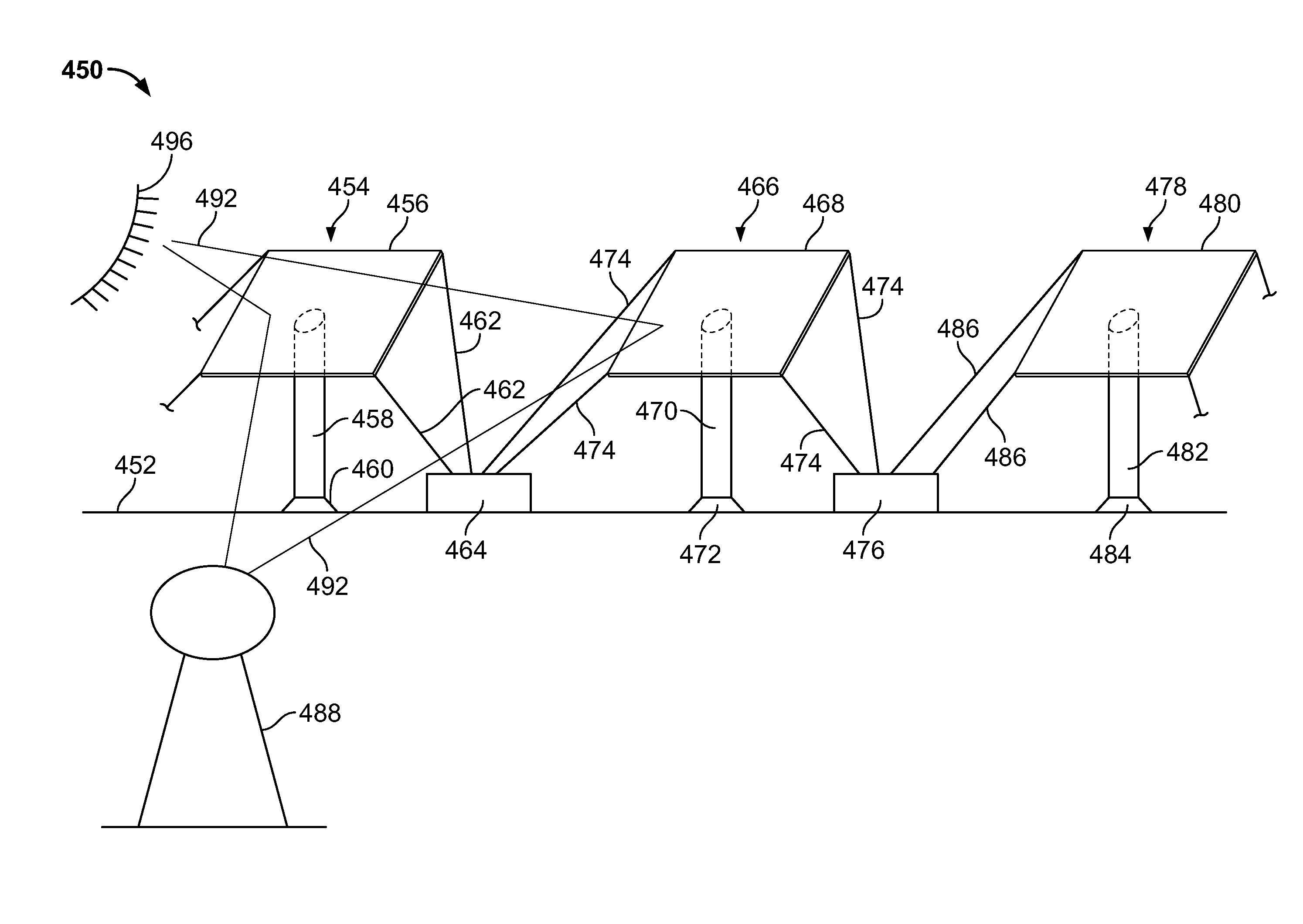
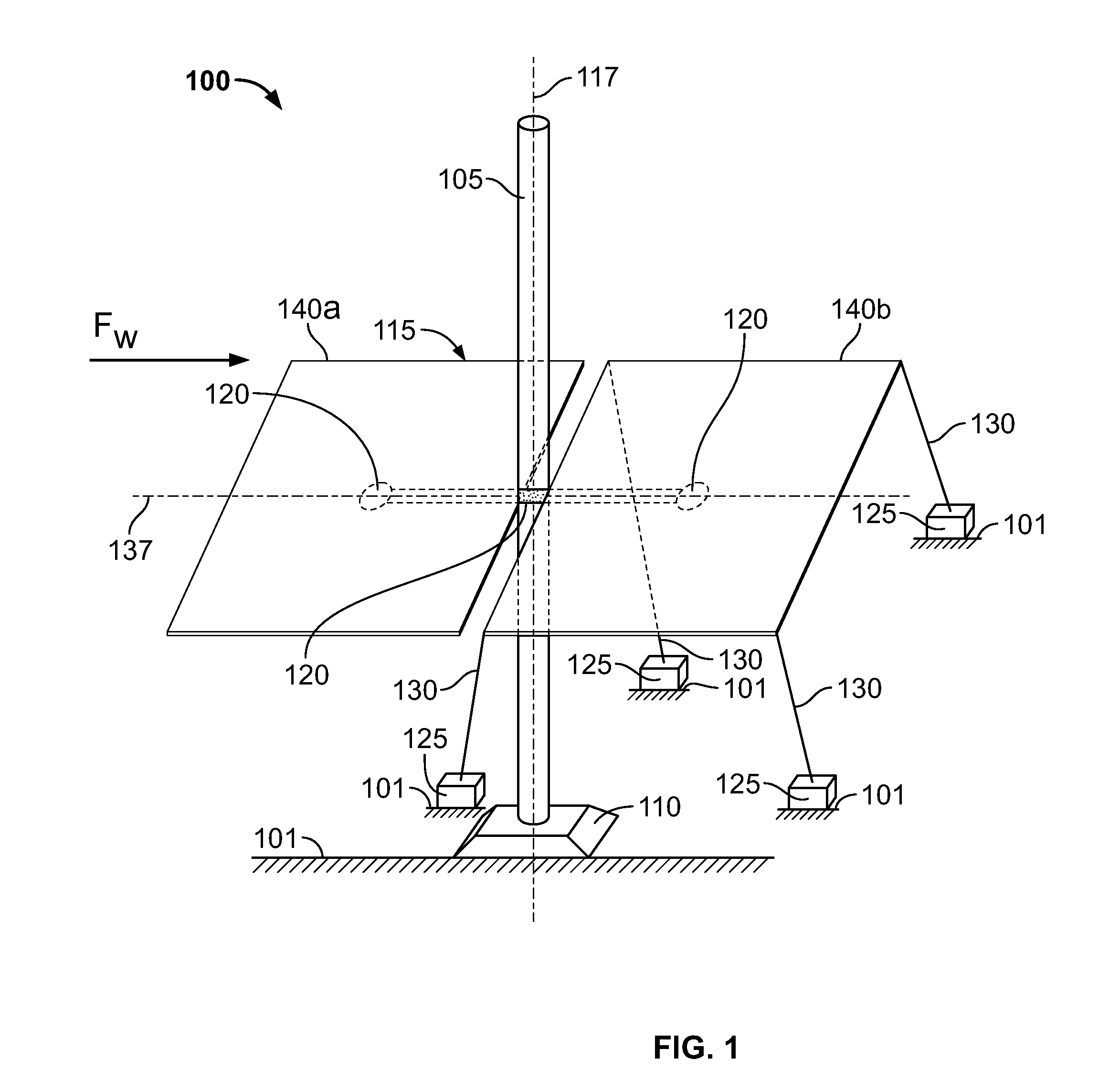
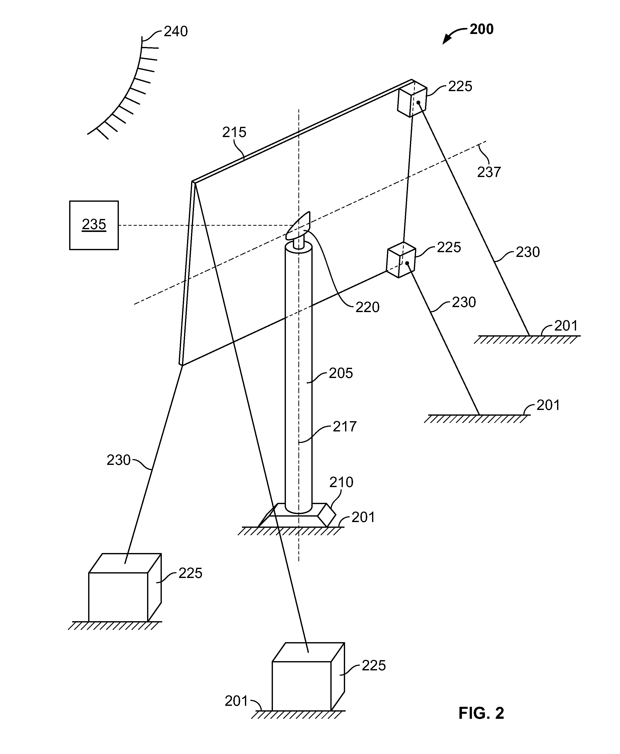
[0050]In some general embodiments, a solar energy system includes a solar energy member, such as a heliostat mirror or PV panel, which is mounted to a substantially vertical support member. One or more actuator assemblies, such as electric motors, are coupled to the solar energy member to facilitate steady-state movement of the solar energy member to track a location of the Sun. The actuator assemblies may further account for other steady-state loads on the solar energy system, such as steady wind loads, and maintain a proper position (e.g., pointing angle) of the solar energy member relative to the Sun. Periodically, the solar energy system may experience one or more transient, or dynamic loads, such as, for example, due to wind gusts. The solar energy system may include one or more damper assemblies to substantially diminish the impact of the transient loads. The damper assembly can include a damper coupled to a spool around which a cable coupled to the solar energy member may be ...


PUM


Abstract

A solar energy system includes a support member secured to a substantially fixed location; a solar energy member mounted to the support member and including a surface operable to track in response to movement of the Sun; an actuator assembly coupled to the solar energy member and configured to periodically apply a torque at a first frequency to move the solar energy member in response to movement of the Sun; and a damper assembly including a spool, where the damper assembly is configured to reactively release and retract a cable about the spool in response to changes in the steady state load, and maintain the cable at a substantially fixed length released from the spool in response to a torque at a second frequency greater than the first frequency that is intermittently received by the solar energy member.

Description

CLAIM OF PRIORITY[0001]This application claims priority under 35 U.S.C. §119(e) to U.S. Provisional Patent Application Ser. No. 61 / 430,233 filed on Jan. 6, 2011, entitled “SYSTEMS AND METHODS FOR SOLAR ENERGY MANAGEMENT,” the entire contents of which are hereby incorporated by reference.TECHNICAL BACKGROUND[0002]This disclosure relates to systems and methods for controlling movement of a solar energy member of a solar energy system.BACKGROUND[0003]Solar energy management, collection, and use can often help alleviate energy problems around the world. In particular, solar energy systems such as photovoltaic (“PV”) systems, which generate electrical energy from solar energy can reduce dependence on fossil fuels or other power generation techniques. Additionally, solar energy may be used to generate heat that can subsequently be used in power generation systems. In some cases, solar energy collection systems may include multiple heliostats that reflect solar energy to a receiver. The re...

Claims


Application Information

Patent Timeline
IPC IPC(8): H01L31/052F24J2/52F24J2/16F24J2/38F24S23/77F24S50/20
CPCG01S3/7861F24J2/4638F24J2/5241F24J2/542H02S20/00F24J2002/5458F24J2002/5496Y02E10/50Y02E10/47F24J2002/1076F24S25/50F24S30/452F24S40/85F24S2023/87F24S2030/133F24S2030/19H02S20/10H02S20/32
Inventor KONINGSTEIN, ROSSDAVIS, BENJAMIN M.ALLEN, TIMOTHY PETERGWON, JUNG SHIA
Owner GOOGLE LLC
Why Eureka
Try Eureka