Oscillating fluid power generator

a technology of fluid power generator and oscillating fluid, which is applied in the direction of electric generator control, machines/engines, manufacturing tools, etc., can solve the problems of wind power itself being subject to controversy, affecting radio frequency transmission, and unsightly windmills, etc., to increase the technical and economic viability of fluid power generation, reduce the purchase cost of fluid energy systems, and harvest fluid

Active Publication Date: 2007-12-27
MORRIS DAVID C
View PDF31 Cites 59 Cited by
  • Summary
  • Abstract
  • Description
  • Claims
  • Application Information

AI Technical Summary

Benefits of technology

[0008] Preferred embodiments of this invention have the potential to harvest fluid (wind or moving water) energy much more cost-effectively than turbines, lower the purchase cost of fluid-energy systems, and increase the technical and economic viability of fluid-power generation. In addition, some wind-power embodiments have the potential to eliminate lethality to birds and bats caused by wind-power systems, overcome public objections to the aesthetics of wind-power structures, and improve public acceptance of wind-power generation. In short, preferred embodiments of this invention have outstanding potential to significantly expand wind power's contribution to the global energy supply.
[0009] Preferred embodiments of the invention exploit the kinetic energy of an aerodynamic, oscillating apparatus, rather than relying on a rotating turbine. The invention was initially developed as a visually pleasing alternative to wind turbines. In preferred embodiments, the system allows for designs that are more compatible with existing architectural forms as well as able to blend more readily into the natural landscape. Initial testing indicates that this new technology also is much more affordable and cost-effective than wind turbines.
[0010] Preliminary wind-tunnel tests and computer modeling of preferred embodiments of this invention, referred to as the “wind fin,” have shown that it is similar if not superior in performance to current state-of-the-art wind turbines of comparable size, at approximately half the system cost. This research suggests that the wind fin technology will be technically and economically feasible for use at many different scales, from small-scale distributed wind systems up to large, utility-scale systems. Initial research also suggests that preferred embodiments of the invention can operate more cost-effectively in lower-speed wind areas than wind turbines. This would facilitate the expansion of wind generation to more prevalent lower-wind sites than are currently being harnessed.
[0012] In preferred embodiments, the wind fin invention is an apparatus for extracting power from a moving fluid stream having a direction of movement, said apparatus comprising three major components: (1) a mast, which in some embodiments anchors the structure, is immobile, and serves as a pivot axis for the wing structure, and in other embodiments serves as a rotatable drive shaft and is supported by a lower support tower; the mast can be guyed for stability or can be free standing; (2) a wing structure that is substantially vertical (plus or minus 5 degrees) in orientation and either is attached to a rotatable sleeve surrounding the mast, which allows the wing structure to swing freely about the mast, or is attached directly to the mast so that the mast rotates back and forth when the wing structure oscillates in the moving fluid stream; the wing structure is composed either of a single symmetrical airfoil or of two or more elements that are attached to each other by hinges; it automatically orients downwind or downstream and responds readily to the moving fluid stream with an oscillating motion; the wing structure's oscillating action is self-sustaining in the moving fluid stream, needs no mechanical assist and is self-starting; wing structures can be constructed in several different ways; for example, they can be constructed like an aircraft wing with a skin that conforms to symmetrical wing ribs or a molded foam core; this skin can be made of fiber reinforced plastic (such as glass fiber reinforced plastic or carbon fiber reinforced plastic), an aircraft fabric covering product (such as Ceconite®), aluminum, or ripstop nylon; in addition, wing structures can be constructed of a rigid material within a frame or be designed to be a self-inflating airfoil, like a parafoil, comprising rows of cells that are open at the front and joined together side by side such that a moving fluid stream keeps the cells inflated; because these wing structures are not subject to the enormous, alternating, bending stresses of wind turbine blades, they can be less complex and much less costly to manufacture; wing structures also can easily be designed in many different color schemes and patterns, making them more visually appealing than wind turbines and able to fit less obtrusively into both built and natural environments; and (3) a power-extraction system that converts the oscillating, bidirectional rotation of the mast or the sleeve surrounding the mast to unidirectional rotation in order to drive an electricity generator, said power-extraction system preferably located at ground level.
[0016] One object of preferred embodiments of the invention is to avoid the tremendous stresses that wind turbine blades need to withstand. Therefore, the wind fins in accordance with these embodiments of the invention can be constructed of lower-cost, less complex, lighter-weight (but highly durable) materials, making power generation with this new technology significantly more affordable and cost-effective. Another object of preferred embodiments of the invention is to function effectively at lower wind speeds. The large wind surface of the wind fins in accordance with this embodiment of the invention, compared to the much smaller wind surface areas of wind turbine blades, creates greater responsiveness to wind force, allowing the new system to function effectively at lower wind speeds than existing wind turbines. Yet another objective of preferred embodiments of the invention is to reduce maintenance requirements. Maintenance is greatly simplified and less costly, because the wind fin is a much simpler system than both (1) conventional horizontal-axis wind turbines, where the fan-like rotor is located at the top of a tower, and (2) vertical-axis wind turbines, where the rotor blades revolve around a vertically aligned axle. In addition, the wind fin's power-extraction system is located at ground level, where it is readily accessible for maintenance. By contrast, the power-extraction system (including generator and gearbox) in horizontal-axis wind turbine designs is located high above the ground, increasing the logistical difficulties and expense of maintenance; in vertical-axis wind turbine systems, it is often located inside the rotating vertical tube, where it is relatively inaccessible for maintenance. A further object of preferred embodiments of the invention is to decrease lethality to birds and bats. The downwind orientation of the oscillating wind fins, combined with their relatively short range of movement and lower speeds than wind turbine blades, prevents this new technology from being lethal to birds and bats. In addition, some embodiments of the oscillating wind fins are expected be far less noisy than wind turbines. Both of these factors should help overcome specific public objections to current wind-turbine technology. Another object of preferred embodiments of the invention is to be more aesthetically pleasing than wind turbines. Its upright, vertical, finned form is more compatible with existing architectural structures than are wind turbines. In addition, wind fins can easily be designed in different color schemes and patterns. Therefore, this new system can blend more readily into both built and natural landscapes. The visual advantages of this new technology will allow it to overcome public objections to wind power on aesthetic grounds.
[0024] In a further preferred embodiment, the invention is an apparatus for extracting power from a moving fluid stream, said apparatus comprising: a mast; a wing structure comprising a combination having one or more vertically oriented airfoil elements that are connected to said mast; and a power take-off mechanism that is driven either directly by a pivoting movement of said mast and said single symmetrical airfoil or by a pivoting movement of said single symmetrical airfoil with said mast remaining stationary; wherein said wing structure is configured to present airfoil surfaces to the moving fluid stream that generate lift first in one direction that is transverse the direction of movement of the moving stream and then in another direction that is opposite said one direction during an oscillation of said wing structure in the moving fluid stream; thereby maximizing the aerodynamic lift of said wing structure in the moving stream, which in turn maximizes the conversion of the energy of the moving stream into useful power.

Problems solved by technology

Unfortunately, wind power itself is not free from controversy as some react with alarm to the prospect of unsightly large windmills dotting the landscape.
Furthermore, turbines can injure or kill birds and bats and interfere with radio frequency (RF) transmissions.
State-of-the-art wind turbines (as well as older wind turbines) have a number of major technical drawbacks that make them expensive to manufacture as well as maintain: (1) they require designs that must overcome great forces at the blade root, including bending in two axes and large torsional loads; they must also resist very large centrifugal forces as well as loading fluctuations caused by wind shadowing from the tower or local ground effect; (2) the towers that support wind turbines must resist high overturning moments at their base due to the very high forces concentrated at the center of the rotor; because of the large rotor blade size in larger systems, towers cannot be guyed; this requires the towers to be constructed of very strong and expensive materials, contributing substantially to the overall system cost; (3) the high-rotation tip speeds of smaller and older large-scale turbines presents a lethal threat to birds and bats; much of the public objection to wind turbines is based on the perception that they contribute to a high death rate for these animals; in addition, many wind turbines are perceived to be noisy; (4) high-lift-capable service equipment is often required for maintenance of the motor / generators that are necessarily located at the top of the wind-turbine towers in horizontal-axis wind turbine systems; (5) in order to withstand very high winds, turbine blades in modern conventional horizontal-axis wind turbine systems must be allowed to feather by rotating the blades approximately 90 degrees along their longitudinal axes, which requires complex and expensive gearing; in Darrieus-type vertical-axis wind turbine systems, the blades cannot be feathered and powerful mechanical brakes or other speed control devices must be employed, increasing the expense of manufacture; (6) Darrieus-type systems are not self-starting and require motors to get the blades rotating at a functional speed; and (7) turbines must be fairly widely spaced to minimize side-by-side and tandem interference with neighboring installations.
In conclusion, relatively expensive materials and sophisticated, costly manufacturing techniques are required for wind turbine components, including blades, gearboxes, bearings, and towers.
In addition, many systems, especially older, utility-scale systems, require costly maintenance.

Method used


Image

  • Oscillating fluid power generator
  • Oscillating fluid power generator
  • Oscillating fluid power generator

Examples


Embodiment Construction

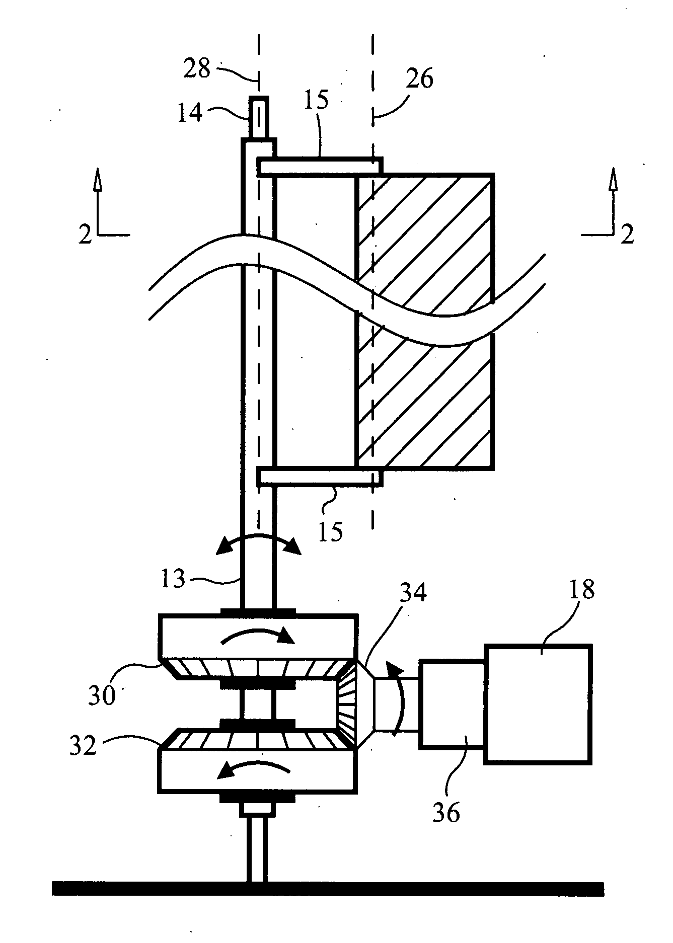
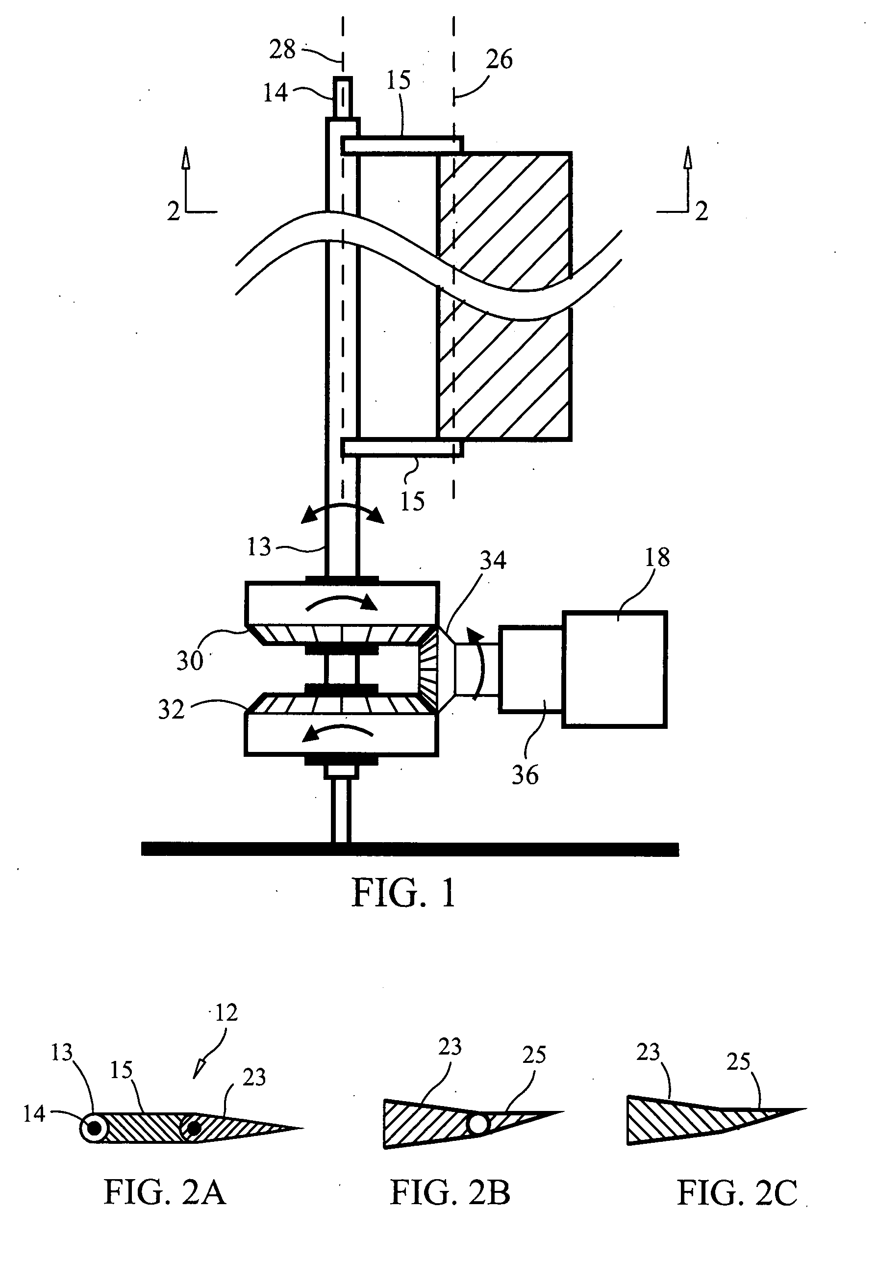
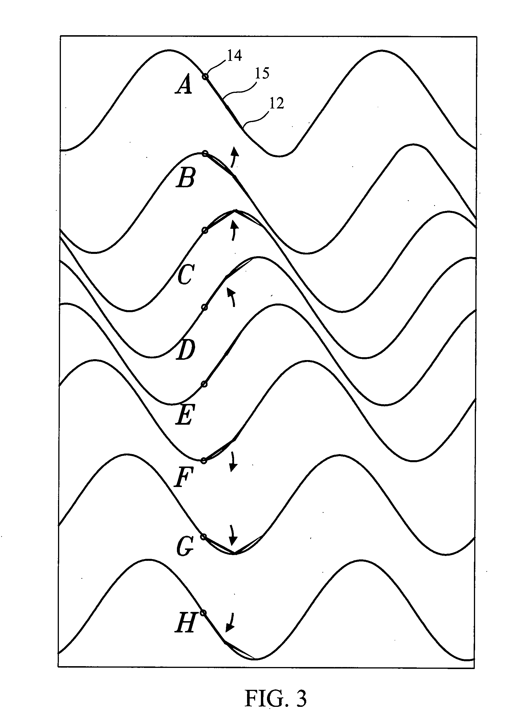
[0117] Referring to FIG. 1, a preferred embodiment of system 10 is presented. In this embodiment, system 10 comprises wing structure 12, mast 14, power takeoff mechanism 16 and generator 18. Preferably, wing structure 12 comprises body 20 and flap 23 with flap 23 being connected to body 20 by means of hinge 24 having hinge axis 26. Body 20 is preferably fixed to sleeve 13 which rotatably mounted on mast 14, and which oscillates around mast pivot axis 28 during operation of system 10. Power takeoff mechanism 16 preferably comprises two overrunning clutches (clockwise clutch 30 and counterclockwise clutch 32), bevel gear 34 and gearbox 36, although any mechanism for converting oscillating motion into rotary motion would suffice. Generator 20 preferably yaws with the wind direction. The stacked and opposing overrunning clutches 30 and 32 are driven by pinions (not shown) attached to sleeve 13. These clutches in turn drive bevel gear 34. This in turn drives gearbox 36 and motor generato...


PUM

PropertyMeasurementUnit
angleaaaaaaaaaa
thickaaaaaaaaaa
densityaaaaaaaaaa

Abstract

A system and method for harvesting the kinetic energy of a fluid flow for power generation with a vertically oriented, aerodynamic wing structure comprising one or more airfoil elements pivotably attached to a mast. When activated by the moving fluid stream, the wing structure oscillates back and forth, generating lift first in one direction then in the opposite direction. This oscillating movement is converted to unidirectional rotational movement in order to provide motive power to an electricity generator. Unlike other oscillating devices, this device is designed to harvest the maximum aerodynamic lift forces available for a given oscillation cycle. Because the system is not subjected to the same intense forces and stresses as turbine systems, it can be constructed less expensively, reducing the cost of electricity generation. The system can be grouped in more compact clusters, be less evident in the landscape, and present reduced risk to avian species.

Description

CROSS-REFERENCE TO RELATED APPLICATIONS [0001] This application is a continuation-in-part of International Patent Application No. PCT / US2006 / 006432, filed on Feb. 24, 2006, which claimed priority in U.S. Provisional Patent Application No. 60 / 656,787, filed Feb. 25, 2005; U.S. Provisional Patent Application No. 60 / 660,880, filed Mar. 10, 2005; U.S. Provisional Patent Application No. 60 / 678,717, filed May 6, 2005; and U.S. Provisional Patent Application No. 60 / 736,489, filed Nov. 14, 2005; the disclosures of which patent applications are incorporated by reference as is fully set forth herein.STATEMENT REGARDING FEDERALLY SPONSORED RESEARCH OR DEVELOPMENT [0002] Not Applicable INCORPORATION-BY-REFERENCE OF MATERIAL SUBMITTED ON A COMPACT DISC [0003] Not Applicable BACKGROUND OF THE INVENTION [0004] This invention relates to a method and system for fluid power generation. In particular, the invention relates to a method and system for fluid power generation by means of an oscillating fl...

Claims


Application Information

Patent Timeline
Patent Type & Authority Applications(United States)
IPC IPC(8): F03D3/00B21K25/00
CPCF03B17/06F03D5/06F05B2210/404F05B2240/302F05B2240/40F05B2260/4031F05B2260/5032Y02E10/20Y02E10/70Y10T29/4932Y02E10/72
Inventor MORRIS, DAVID
Owner MORRIS DAVID C
Why Eureka
Try Eureka