Liquid discharging apparatus, head unit, integrated circuit device for capacitive load driving, and capacitive load driving circuit

a technology of capacitive load and liquid discharging apparatus, which is applied in the direction of printing, etc., can solve the problems of gate driver or boosting circuit being a source of noise, affecting the quality of printing, and affecting the effect of noise, etc., to achieve excellent accuracy, suppress the influence of noise, and high accuracy

Active Publication Date: 2016-12-20
SEIKO EPSON CORP
View PDF10 Cites 1 Cited by
  • Summary
  • Abstract
  • Description
  • Claims
  • Application Information

AI Technical Summary

Benefits of technology

[0008]An advantage of some aspects of the invention is to provide a liquid discharging apparatus, a head unit, an integrated circuit device for capacitive load driving, and a capacitive load driving circuit, in which the discharge accuracy of liquid can be improved.
[0011]In this case, since the second high voltage system circuit block which does not perform the switching operation is disposed between the low voltage system circuit block and the first high voltage system circuit block which performs the switching operation, it is possible to suppress the influence of noise due to the switching operation of the first high voltage system circuit block on the low voltage system circuit block. Accordingly, the modulation portion which is included in the low voltage system circuit block can generate a modulation signal which has excellent accuracy. Therefore, since it is possible to control the voltage applied to the piezoelectric element with high accuracy, it is possible to realize a liquid discharging apparatus in which the discharge accuracy of liquid can be improved.Application Example 2
[0032]In this case, since the second high voltage system circuit block which does not perform the switching operation is disposed between the low voltage system circuit block and the first high voltage system circuit block which performs the switching operation, it is possible to suppress the influence of noise due to the switching operation of the first high voltage system circuit block on the low voltage system circuit block. Accordingly, the modulation portion which is included in the low voltage system circuit block can generate a modulation signal which has excellent accuracy. Therefore, it is possible to realize a capacitive load driving circuit in which the voltage applied to the capacitive load can be controlled with high accuracy.

Problems solved by technology

However, due to the high oscillation frequency, the influence of various types of noise is likely to occur.
In this case, since the gate driver or the boosting circuit which is included in the first high voltage system circuit block performs the switching operation, the gate driver or the boosting circuit can be a source of noise.
When the waveform of the driving signal is blunt, the displacement of the piezoelectric element which is operated in accordance with a rising or falling edge of the waveform becomes slow, tailing during discharge or a discharge defect is generated, and the quality of printing deteriorates.
However, as switching frequency increases in the transistor, switching loss increases, and compared to linear amplification of a class-AB amplifier or the like, excellent power saving performance and generated heat saving performance are deteriorated.

Method used


Image

  • Liquid discharging apparatus, head unit, integrated circuit device for capacitive load driving, and capacitive load driving circuit
  • Liquid discharging apparatus, head unit, integrated circuit device for capacitive load driving, and capacitive load driving circuit
  • Liquid discharging apparatus, head unit, integrated circuit device for capacitive load driving, and capacitive load driving circuit

Examples


Embodiment Construction

[0047]Hereinafter, an appropriate embodiment of the invention will be described in detail by using the drawings. The drawings used are for convenience of the description. In addition, the embodiment which will be described hereinafter does not inappropriately limit the contents of the invention described within the range of the patent claims. All of the configurations which will be described hereinafter are not necessarily essential configuration requirements of the invention.

1. Outline of Liquid Discharging Apparatus

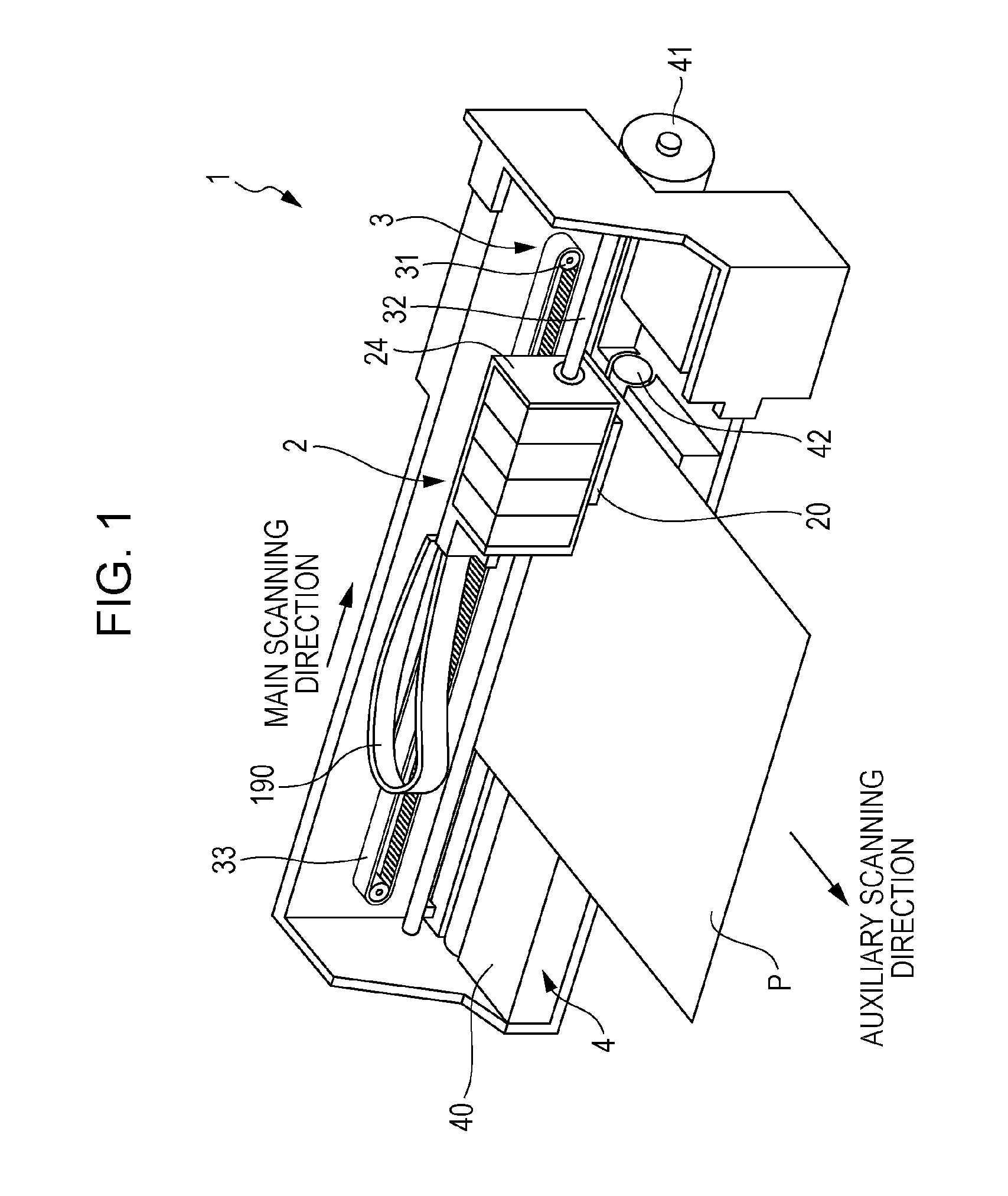
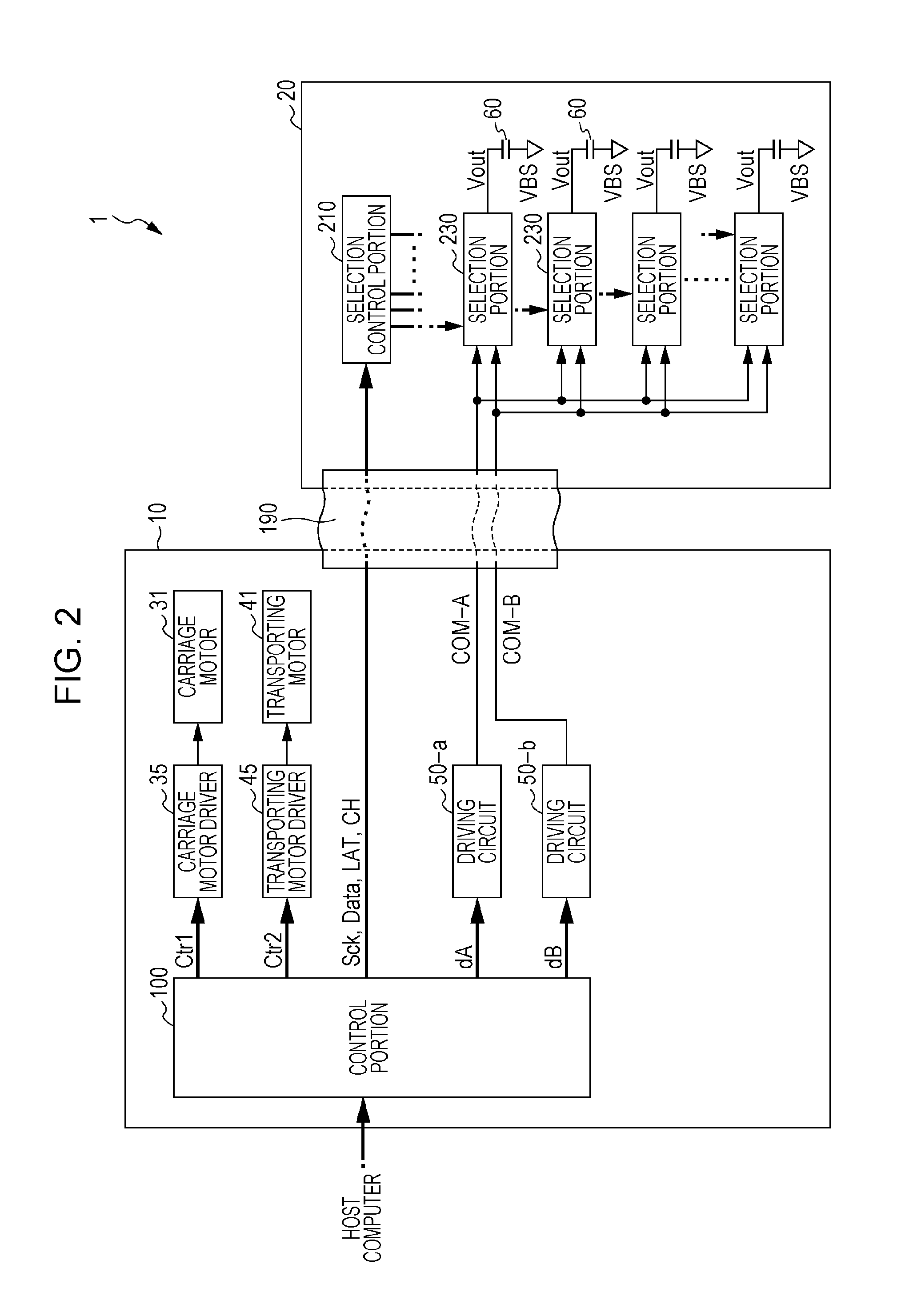
[0048]A printing apparatus which is an example of a liquid discharging apparatus according to the embodiment is an ink jet printer which forms an ink dot group on a printing medium, such as a paper sheet by discharging ink in accordance with image data supplied from an external host computer, and accordingly, prints an image (including characters or figures) which corresponds to the image data.

[0049]Examples of the liquid discharging apparatus include a printing apparat...


PUM


Abstract

There is provided a liquid discharging apparatus including: a low voltage system circuit block including a modulation portion which generates a modulation signal pulse-modulated from a source signal; a transistor which generates an amplification modulation signal amplified from the modulation signal; a first high voltage system circuit block which receives the signal from the low voltage system circuit block and performs a switching operation; a second high voltage system circuit block which does not perform the switching operation; a low pass filter which demodulates the amplification modulation signal and generates a driving signal; and a piezoelectric element which is displaced as the driving signal is applied, in which the second high voltage system circuit block is disposed between the low voltage system circuit block and the first high voltage system circuit block.

Description

[0001]The entire disclosure of Japanese Patent Application No. 2014-250668, filed Dec. 11, 2014 is expressly incorporated by reference herein.BACKGROUND[0002]Technical Field[0003]The present invention relates to a liquid discharging apparatus, a head unit, an integrated circuit device for capacitive load driving, and a capacitive load driving circuit.[0004]Related Art[0005]In a liquid discharging apparatus, such as an ink jet printer, which discharges ink and prints an image or a document, an apparatus which uses a piezoelectric element (for example, a piezo element) has been known. The piezoelectric elements are provided corresponding to each of a plurality of nozzles in a head unit, and each of the piezoelectric elements is driven in accordance with driving signals. Accordingly, a predetermined amount of ink (liquid) is discharged from the nozzle at a predetermined timing, and a dot is formed. Since the piezoelectric element is a capacitive load, such as a capacitor, in terms of e...

Claims


Application Information

Patent Timeline
Patent Type & Authority Patents(United States)
IPC IPC(8): B41J2/045B41J2/14
CPCB41J2/04541B41J2/04581B41J2/14233B41J2002/14491
Inventor YAMADA, TOMOKAZU
Owner SEIKO EPSON CORP
Why Eureka
Try Eureka