Method for determining current eccentricity of rotating rotor and method of diagnostics of eccentricity of rotating rotor

a technology of rotating rotor and current eccentricity, which is applied in the direction of vibration measurement, measurement devices, instruments, etc., can solve the problems of damage to the machine, ineffective flexibility ineffective dynamic excitation forces of the rotor or the rotor system, etc., and achieve the effect of resistance to measuring signal errors

Active Publication Date: 2017-03-14
DOOSAN SKODA POWER
View PDF2 Cites 0 Cited by
  • Summary
  • Abstract
  • Description
  • Claims
  • Application Information

AI Technical Summary

Problems solved by technology

In the area of rotors and rotor systems eccentricity means deformation of the rotor or the rotor system in the sense of a bend showing itself when the rotor is being rotated at low revolutions (e.g. by means of turning gear), at which dynamic excitation forces (e.g. from rotating unbalance) and flexibility of the rotor or the rotor system are not effective.
If the eccentricity of the rotor or the rotor system is not discovered in time, it can cause damages of the machine and, in extreme cases, its complete breakdown.
This danger is increased especially within a band of critical speeds (natural frequencies) where up to multiple increase of amplitude of vibrations of the rotor or rotor system occurs, being caused by high amplitude of excitation force from an unbalance (from the point of view of analysis of dynamic features, the bend itself behaves as an unbalance) as well as by resonance amplification.
The method requires increased attention of service personnel and its considerable experiences, which is its major disadvantage.
However, both methods may lead to considerably distorted results that could be inconsistent with reality, because the eccentricity of the rotor or the rotor system cannot be uniquely determined solely from time series of measured signals, without appropriate reference signal.
None of the current methods thus leads to unique determination of the eccentricity of the rotor or the rotor system, and does not allow its exact diagnostics.

Method used


Image

  • Method for determining current eccentricity of rotating rotor and method of diagnostics of eccentricity of rotating rotor
  • Method for determining current eccentricity of rotating rotor and method of diagnostics of eccentricity of rotating rotor
  • Method for determining current eccentricity of rotating rotor and method of diagnostics of eccentricity of rotating rotor

Examples


Embodiment Construction

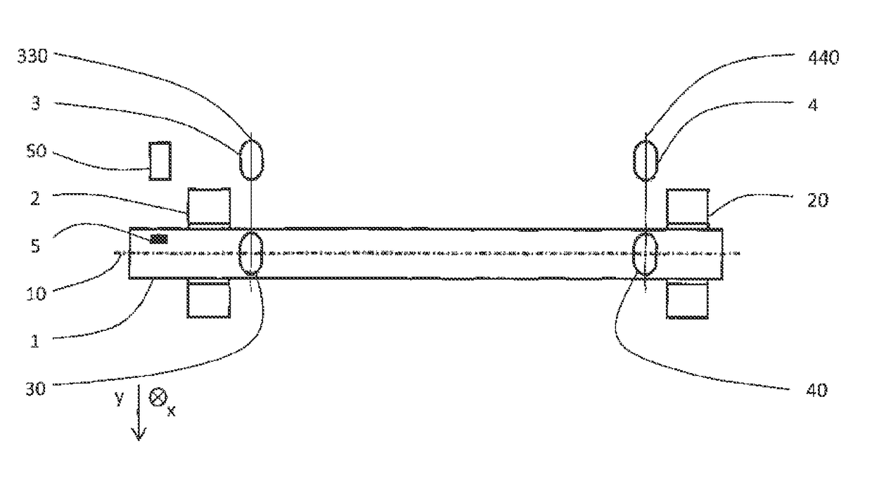
[0023]The method for determining current eccentricity of rotating rotor according to the invention will be described on example of determining eccentricity of steam turbine rotating rotor 1 shown in FIG. 1. This rotor 1 is mounted in two radial bearings 2 and, 20 while is scanned near each of them by pair of sensors 3, 30 and 4, 40 for measuring relative rotor vibrations, which are located in planes 330 and 440 of measuring perpendicular to the axis 10 of rotor 1, at equal distance from it, whereas sensors 3, 30 and 4, 40 of each pair are mutually shifted by 90° in the tangential direction. Besides that, the rotor 1 is outside of the planes 330 and 440 of measuring equipped by phase marker 5, and is scanned at the point of its location by sensor 50 of the phase marker 5. The phase marker 5 and all sensors 3, 30, 4, 40, 50 are standard parts of field instrumentation of steam turbine rotor 1 and have been used only for determining the speed of its rotation and its relative vibrations ...


PUM


Abstract

A method is provided for determining current eccentricity of a rotating rotor which is equipped with a phase marker scanned at constant speed of rotation up to 500 rpm by a sensor of a phase marker at the point of the phase marker, and outside of the phase marker by at least one sensor of relative rotor vibrations, while after digitizing the signals of the sensors, estimates current position of the phasor of the 1st harmonic component of signal of the sensor of relative rotor vibrations in the complex plane, which is subsequently compared to a reference position of the phasor of the 1st harmonic component, which has been determined in advance, whereas the variation vector of the phasors is an image of eccentricity of the rotor. Further, a method of diagnostics of eccentricity of a rotating rotor is based on this method for determining current eccentricity.

Description

CROSS REFERENCE TO RELATED APPLICATIONS[0001]This is a National Stage of International Application No. PCT / CZ2012 / 000094 filed Sep. 20, 2012, claiming priority based on Czech Republic Patent Application No. PV 2011-588 filed Sep. 21, 2011, the contents of all of which are hereby incorporated by reference in their entirety.TECHNICAL FIELD[0002]The invention relates to a method for determining current eccentricity of rotating rotor.[0003]The invention also relates to a method of diagnostics of eccentricity of rotating rotor.BACKGROUND ART[0004]In the area of rotors and rotor systems eccentricity means deformation of the rotor or the rotor system in the sense of a bend showing itself when the rotor is being rotated at low revolutions (e.g. by means of turning gear), at which dynamic excitation forces (e.g. from rotating unbalance) and flexibility of the rotor or the rotor system are not effective. With steam turbines for instance, the deformation is usually caused by heterogeneous temp...

Claims


Application Information

Patent Timeline
Patent Type & Authority Patents(United States)
IPC IPC(8): G01H1/00G01M15/14G01M1/16G01M1/22
CPCG01M1/16G01M1/22G01M15/14G01H1/003G01M1/08
Inventor VOSEJPKA, JANCERNY, VACLAV
Owner DOOSAN SKODA POWER
Why Eureka
Try Eureka