Unlock instant, AI-driven research and patent intelligence for your innovation.

Non-volatile semiconductor memory with high reliability and data erasing method thereof

a non-volatile semiconductor and memory technology, applied in the field of reliability of an nand or an nor flash memory, can solve the problems of corruption of data left, poor writing, and inability to ensure reliability, and achieve the effect of suppressing the reliability deterioration

Active Publication Date: 2017-07-25
WINBOND ELECTRONICS CORP
View PDF17 Cites 0 Cited by
  • Summary
  • Abstract
  • Description
  • Claims
  • Application Information

AI Technical Summary

Benefits of technology

[0017]Accordingly, the invention provides a non-volatile semiconductor memory apparatus capable of suppressing the reliability deterioration caused by data writing.
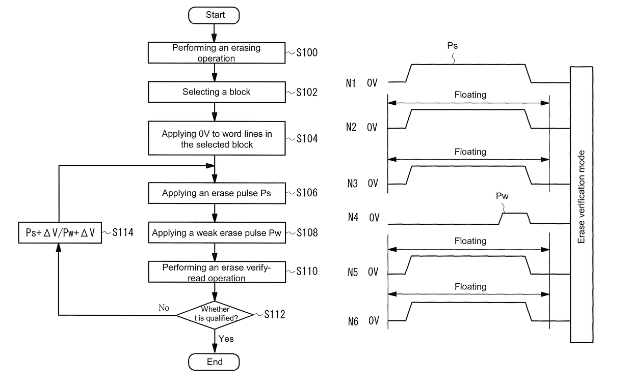
[0018]In a period of the verify-read operation after the erase pulse is applied, the deterioration may occur in the oxide film. Thus, in a preferred embodiment of the invention, a weak erase pulse is applied immediately after each erase pulse is applied. Preferably, the weak erase pulse is set to a positive voltage lower than the positive voltage of the erase pulse commonly applied to the P well which is used to set the word lines of the selected block to 0 V or a lower positive voltage than that of the P well. If the potential of the P well is set to be lower, the tunnel current of electrons flowing from the floating gate toward the silicon substrate does not occur. Therefore, the threshold of the memory cells is not changed, and the application of the weak erase pulse may achieve suppressing the deterioration in reliability of the oxide film.
[0019]In the non-volatile semiconductor memory apparatus of a further preferred embodiment, after the control gate is set to 0 V or a positive voltage lower than the P well, and a positive erase pulse is applied to the N well and the P well under the memory cell array, and the electrons are emitted from the floating gate (i.e., the charge accumulation layer) to the silicon substrate, the control gate is again set to 0 V or the positive voltage lower than the P well (in the same manner as above), the initial erase pulse plus a pulse with a positive voltage lower than that of the initial erase pulse applied to the N well and P well are set as a set, and the set of the pulses are applied when the next erase pulse is to be applied. In the time of the pulses applied to the N well and the P well after the erase pulse is applied, it is preferable to prevent the electrons from emitting from the floating gate toward the silicon substrate.
[0020]In a further preferred embodiment, after the control gate is set to 0 V, the positive pulse is applied to the N well and the P well under the memory cell array, and the electrons are emitted from the floating gate to the silicon substrate, a peak of the pulse applied to the N well and the P well is reduced in the same process of applying the pulses. The potential provided to the N well and the P well is reduced in the middle of the process, so as to prevent the electrons from emitting from the floating gate toward the silicon substrate.
[0021]In a further preferred embodiment, after the control gate is set to 0 V, the positive erase pulse is applied to the N well and the P well under the memory cell array, and the electrons are emitted from the floating gate to the silicon substrate, the potential of the control gate is increased from 0 V in the same process of applying the pulses, and the potential of the control gate is returned to 0 V after the process of applying the positive erase pulse to the N well and the P well is completed. The potential of the control gate is increased from 0 V in the middle of the process, so as to prevent the electrons from emitting from the floating gate toward the silicon substrate and prevent the electrons from injecting from the silicon substrate toward the floating gate.
[0022]To sum up, the invention can suppress deterioration of the gate oxide film caused by repeated data writing, so as to increase the number of times for data rewriting that can ensure the reliability.

Problems solved by technology

In the conventional NAND flash memory, repeatedly performed writing / erasing operations result in deterioration in the oxide film under the floating gate, which usually causes poor writing due to the increase in the range of the threshold distribution width during data reading, or causes corruption of the data left over after the data writing operation.
Otherwise, the reliability cannot be ensured if the number is over a threshold.
Therefore, it is assumed that the left-over after the erase pulse is applied may cause the oxide film deterioration.
Such oxide film deterioration causes deterioration in reliability to miniaturized memory cells and results in the reduction of the times for the rewriting operation that may maintain the reliability.
In a period of the verify-read operation after the erase pulse is applied, the deterioration may occur in the oxide film.

Method used


Image

  • Non-volatile semiconductor memory with high reliability and data erasing method thereof
  • Non-volatile semiconductor memory with high reliability and data erasing method thereof
  • Non-volatile semiconductor memory with high reliability and data erasing method thereof

Examples


Embodiment Construction

[0045]Various aspects of the implementation of the invention will be described in detail with reference to the accompanying drawings hereinafter. It should be noted that for the sake for comprehension, each element is exaggerated, and the ratio of each element is not the same as each actual element.

[0046]FIG. 5 is a block diagram illustrating an exemplary structure of an NAND flash memory according to an embodiment of the invention. A flash memory 100 includes a memory array 110 in which a plurality of memory cells arranged in an matrix, an input / output (I / O) buffer 120 connected to an external I / O terminal I / O and maintaining I / O data, an address register 130 for receiving address data from the I / O buffer 120, a data register 140 for maintaining the I / O data, a controller 150 for generating control signals C1, C2 and C3 configured to control each part based on command data and external control signals (e.g., chip enable or address latch enable signals that are not shown) from the I...


PUM


Abstract

A non-volatile semiconductor memory apparatus and a data erasing method thereof are provided to suppress deterioration in reliability due to data rewriting. An erasing method of a flash memory is provided, which includes the following steps. A control gate is maintained at 0V, a high-voltage erase pulse is applied to a P well, such that electrons is emitted from a floating gate to the P well. Then, the control gate is again maintained, and a weak erase pulse with a voltage lower than the erase pulse is applied to the P well.

Description

CROSS-REFERENCE TO RELATED APPLICATION[0001]This application claims the priority benefit of Japan application serial no. 2014-204065, filed on Oct. 2, 2014. The entirety of the above-mentioned patent application is hereby incorporated by reference herein and made a part of this specification.BACKGROUND[0002]Field of the Invention[0003]The invention relates to the reliability of an NAND or an NOR flash memory and a method for providing a flash memory with less reliability deterioration even a writing and an erasing operations are repeatedly performed.[0004]Description of Related Art[0005]FIG. 1 is a schematic cross-sectional diagram illustrating a structure of a cell array of an NAND flash memory. FIG. 2 is an equivalent circuit diagram of the cell array. An N well 12 is formed in a P-type silicon substrate 10. A P well 14 is formed in the N well 12. A plurality of transistors, which constitutes a NAND string, are formed on the P well 14. An NAND string includes a plurality of memory...

Claims


Application Information

Patent Timeline
Patent Type & Authority Patents(United States)
IPC IPC(8): G11C11/34G11C16/16G11C16/34G11C16/14G11C16/04G11C11/56
CPCG11C16/14G11C11/5635G11C16/16G11C16/3445G11C16/0483
Inventor SHIROTA, RIICHIRO
Owner WINBOND ELECTRONICS CORP