Skin treatment system

a skin treatment and skin technology, applied in the field of skin treatment system, can solve the problems of not all energy is absorbed in the skin, the hair removal effect the energy invested in light frequencies is not effective or sufficiently effective, so as to prevent or limit the possibility of pain, the effect of reducing the pain

Active Publication Date: 2017-08-08
KONINKLIJKE PHILIPS ELECTRONICS NV
View PDF20 Cites 0 Cited by
  • Summary
  • Abstract
  • Description
  • Claims
  • Application Information

AI Technical Summary

Benefits of technology

[0006]Generally speaking, it is possible to divide the energy in a light pulse into three portions: 1) reflected by the skin; 2) absorbed by the skin but not effective in hair removal; 3) absorbed by the skin and effective in hair removal. Further, there will also be an energy loss in the conversion from electrical power to light power, which, together with the rejected light energy, will contribute to heating the apparatus or parts of it. The energy absorbed in the skin will cause a temperature rise in the skin. Now, on the one hand, the energy input into the skin should be sufficiently high to cause the destruction of the follicles and hence the falling out of hair, but on the other hand the thermal effects should be limited so as to prevent or in any case limit possible pain sensations.

Problems solved by technology

In light pulse hair removal systems, there is a problem relating to temperature.
Thus, energy is invested in light frequencies that are not effective or not sufficiently effective in the process of hair removal.
Further, not all energy is absorbed in the skin.
Further, it has been found that people respond differently to the light treatment, possibly caused by differences in skin characteristics.
Further, there will also be an energy loss in the conversion from electrical power to light power, which, together with the rejected light energy, will contribute to heating the apparatus or parts of it.

Method used


Image

  • Skin treatment system
  • Skin treatment system
  • Skin treatment system

Examples


Embodiment Construction

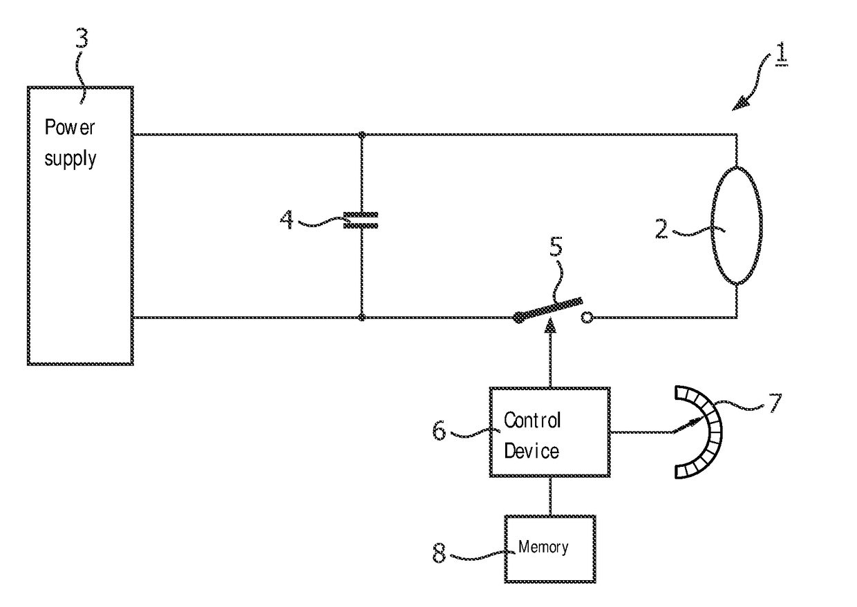
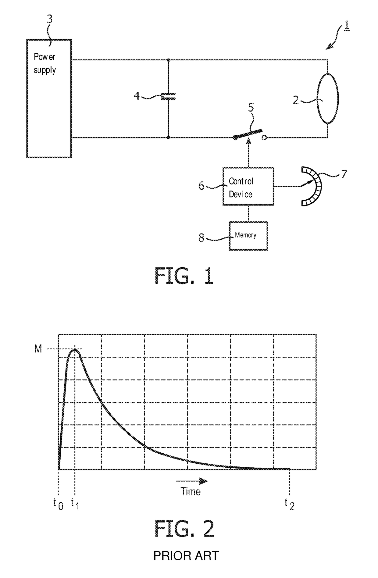
[0018]FIG. 1 schematically shows an electrical block diagram of a skin treatment system 1 according to the present invention, comprising a flashlamp 2. The flashlamp 2 is a discharge lamp, including a gas-filled vessel with two electrodes, as known per se. Although other types of flashlamps are possible, the flashlamp 2 typically is a xenon discharge lamp. A discharge capacitor 4 is mounted in parallel with the lamp 2, with a controllable switch 5 arranged in a current path between the lamp 2 and the capacitor 4. The capacitor 4 is supplied from a power source 3, typically a voltage source. The controllable switch 5 is controlled by a control device 6, for instance a microprocessor or the like.

[0019]FIG. 2 is a graph, showing lamp current density as a function of time, for illustrating prior art operation of such a flash lamp. First, the capacitor 4 is charged from the source 3. The switch 5 is open (i.e. non-conductive). At a certain moment t0, the control device 6 closes the switc...


PUM


Abstract

A method of operating a flashlamp (2) in a skin treatment system (1) comprises the steps of establishing a conductive path between the flashlamp (2) and a charged capacitor (4) causing a free discharge within the flashlamp, and interrupting said conductive path so as to cut off the current through the lamp when the current density drops below a predetermined current density threshold level (Ix) or when the energy applied to the skin reaches a certain maximum (EM).

Description

FIELD OF THE INVENTION[0001]The present invention relates in general to a skin treatment system, especially a hair removal system, on the basis of intense pulsed light. In the following, the present invention will be specifically explained for a hair removal system, but the gist of the invention can be more generally applied in skin treatment systems.BACKGROUND OF THE INVENTION[0002]The desire to remove (human) body hair is quite old, and many systems have been developed for meeting this desire. For instance, there are mechanical systems operating on the basis of mechanically cutting or pulling out the hairs. A more recent development is applying light pulses of a high intensity to a portion of the skin where the hair is to be removed. This technique is known per se, so that an elaborate explanation may be omitted here. Suffice it to say that light energy is absorbed in the skin and destroys the follicles so that the hair will fall out. An advantage is that the hair removal is more ...

Claims


Application Information

Patent Timeline
Patent Type & Authority Patents(United States)
IPC IPC(8): A61B18/20H05B41/30A61B18/00A61N5/06A61B17/00
CPCA61B18/203H05B41/30A61B2017/00154A61B2018/00476A61N2005/0654
Inventor LUTSCHOUNIG, MARIO ARNOLDMIKULA, CHRISTIANWEICHSLER, WALTER JULIUSGASSER, RENE
Owner KONINKLIJKE PHILIPS ELECTRONICS NV
Why Eureka
Try Eureka