Wide field angle projection system and projection-type image display apparatus

a projection system and projection type technology, applied in the field of wide field angle projection system and projection type image display apparatus, can solve the problem that each projection system is therefore insufficient in an application for a large screen, and achieve the effect of wide field angle, high luminance and high resolution

Active Publication Date: 2017-08-22
SEIKO EPSON CORP
View PDF5 Cites 2 Cited by
  • Summary
  • Abstract
  • Description
  • Claims
  • Application Information

AI Technical Summary

Benefits of technology

[0006]An advantage of some aspects of the invention is to provide a projection system capable of achieving not only high luminance and high resolution but also a wide field angle.

Problems solved by technology

Each of the projection systems is therefore insufficient in an application for a large screen in some cases because the distance between the projector and a screen is short.

Method used


Image

  • Wide field angle projection system and projection-type image display apparatus
  • Wide field angle projection system and projection-type image display apparatus
  • Wide field angle projection system and projection-type image display apparatus

Examples


example 1

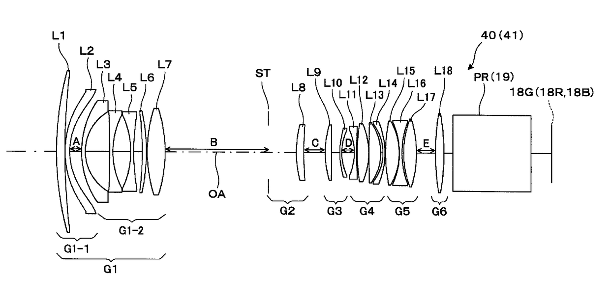
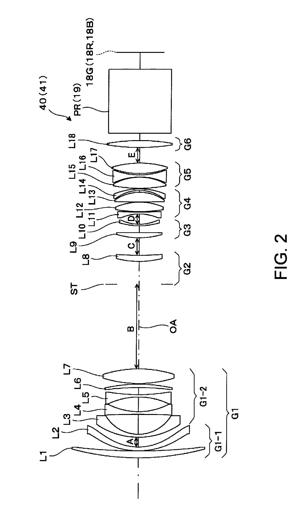
[0070]Table 1 shown below shows data on the lens surfaces of a projection lens according to Example 1. In Table 1 and other tables, “INF” stands for ∞.

[0071]

TABLE 1SurfacenumberElementGroupRDndνd0SCINFOBJ1L11-1335.3769.0761.5163364.12702.8360.3003L2105.4395.0001.5311656.0471.594A5L31-296.7724.0001.8466623.8650.13126.5307L4−1007.6243.5001.6180063.4886.20019.4989L5−92.0243.2001.4370095.110242.9509.33711L6−335.7524.4601.8466623.812−205.3841.00013L7156.74219.4431.6034238.014−153.835B15ST2INF35.27616L8120.3208.2071.6989530.117373.545C18L93105.4776.7671.4874970.519−1968.3269.25320L1093.7802.0001.4970081.52157.203D22L114−60.9402.6001.9036631.323490.0860.57924L12190.11412.5751.8061033.325−79.7290.30026L131107.21112.8511.4970081.527−56.6742.47328L14−51.4562.0001.8061033.329−87.986E30L155176.14414.8941.4370095.131−68.9840.20032L16−80.1852.8001.8061033.33394.5071.86634L17104.78813.9541.4370095.135−123.359F36L186265.6769.2831.8080922.837−244.8161038DPINF851.516864.239INF22.4840LVINF0.00

[0072]Ta...

example 2

[0082]Table 5 shown below shows data on the lens surfaces of a projection system according to Example 2.

[0083]

TABLE 5SurfacenumberElementGroupRDndνd0SCINFOBJ1L11-1348.9039.8311.5163364.12824.4050.3003L2115.4965.0001.5311656.0477.261A5L31-295.1794.0001.8466623.8650.32823.6657L4243.4293.5001.4970081.5866.73221.2699L5−112.2973.4061.4670081.510122.3400.30011L697.27515.7181.5163364.112−1587.133B13L721045.1869.4621.8466623.814−266.623C15L83114.1306.6541.7234238.016193.518D17L94107.36311.8671.4874970.218−2063.8369.46119L10102.0992.0001.4370095.12060.410E21L115−61.4052.6001.9036631.322497.2810.55323L12191.82612.5981.8061033.324−81.7230.30025L13576.70912.8841.4970081.526−60.6672.34827L14−55.5062.0001.8061033.328−90.596F29L156149.43515.0371.4370095.130−75.2730.70531L16−80.9302.8001.8061033.33293.4871.70733L17101.03515.2721.4370095.134−116.868G35L187229.3358.8001.8080922.836−334.28910.00037DPINF80.0001.516864.238INF22.67340LVINF0

[0084]Table 6 shown below shows aspheric coefficients of a third ...

example 3

[0094]Table 9 shown below shows data on the lens surfaces of a projection system according to Example 3.

[0095]

TABLE 9SurfacenumberElementGroupRDndνd0SCINFOBJ1L11-1297.83010.3801.5163364.12663.9620.3003L2108.9475.0001.5311656.0473.023A5L31-292.5204.0001.8466623.8648.90726.9257L4−787.2823.5001.6180063.4883.70119.1519L5−90.4575.0001.4370095.110337.199B11L62−161.9084.2091.8466623.812−130.1901.00013L7163.93818.5831.6034238.014−157.341C15ST3INF33.16516L8110.40412.3711.6989530.117283.989D18L94115.3916.8401.4874970.219−622.82111.85120L1084.2932.0001.4970081.52153.174E22L115−62.4552.6001.9036631.323452.2160.69724L12189.91711.6981.8061033.325−87.6320.30026L131539.78412.9581.4970081.527−53.1782.36028L14−48.7982.0001.8061033.329−87.500F30L156164.10915.1951.4370095.131−68.9830.20032L16−87.0512.8001.8061033.33394.4681.80434L17103.82414.1631.4370095.135−121.317G36L187218.3229.6741.8080922.837DP−288.92710.00038INF80.0001.516864.239LVINF22.691

[0096]Table 10 shown below shows aspheric coefficients of...


PUM


Abstract

A projection system includes a first lens group to an n-th lens group with n being 6 or 7 sequentially arranged from a enlargement side. The first lens group includes a first-first lens group and a first-second lens group sequentially arranged from the enlargement side. The two lens groups are separated from each other by a variable distance for image plane correction. The first lens group and the n-th lens group are fixed and the second lens group to the (n−1)-th group are moved when the magnification is changed. The following conditional expression is satisfied: 2<BF / fw<2.8, where fw represents the focal length of the projection system operating at the wide angle end, and BF represents the air conversion length of the back focal distance of the projection system.

Description

BACKGROUND[0001]1. Technical Field[0002]The present invention relates to a projection system suitable to be incorporated in a projector that enlarges and projects an image formed on an image display device and a projection-type image display apparatus that incorporates the projection system.[0003]2. Related Art[0004]In recent years, in a high-luminance (at least 10,000 lumens (lm), for example), high-resolution projector, it is desired to perform wide-field-angle image projection. JP-A-2010-152277 and JP-A-2011-107200 each disclose a projection system capable of achieving high luminance and high resolution. The projection system described in JP-A-2010-152277 is formed of first to sixth groups in each of which each lens is a single lens, and the magnification is changed by movement of the second to fifth groups with the first and sixth groups fixed. The projection system described in JP-A-2011-107200 is formed of first to sixth groups in each of which each lens is a single lens, and ...

Claims


Application Information

Patent Timeline
Patent Type & Authority Patents(United States)
IPC IPC(8): G03B21/14G02B13/18G02B15/177G02B15/20G02B13/16
CPCG03B21/142G02B13/16G02B13/18G02B15/177G02B15/20G02B15/173G02B15/146
Inventor SHIOKAWA, KOJI
Owner SEIKO EPSON CORP
Why Eureka
Try Eureka