Rotating assembly for a turbomachine

Active Publication Date: 2017-10-10
SN DETUDE & DE CONSTR DE MOTEURS DAVIATION S N E C M A
View PDF24 Cites 0 Cited by
  • Summary
  • Abstract
  • Description
  • Claims
  • Application Information

AI Technical Summary

Benefits of technology

[0013]The present invention offers a simple, efficient and economical solution to the sealing probl

Problems solved by technology

Problems however exist, which concern sealing and eff

Method used


Image

  • Rotating assembly for a turbomachine
  • Rotating assembly for a turbomachine
  • Rotating assembly for a turbomachine

Examples


Embodiment Construction

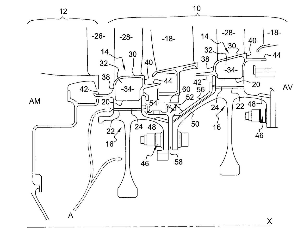
[0048]Reference is first made to FIG. 1 which shows a low-pressure turbine 10 according to the technique of the prior art, arranged downstream of a high-pressure turbine 12. The low-pressure turbine 10 comprises axially alternating stages of annular rows of stationary blades 18, called distributors, and stages of rotating discs 16 provided on their periphery with a plurality of blades 14, with such stages being arranged around the X axis of the turbomachine.

[0049]In the present document, like in the technical field concerned, the terms upstream AM and downstream AV are so defined that upstream is axially on the side where the general flow of the turbomachine comes from, and downstream is axially on the side where the same flow flows to.

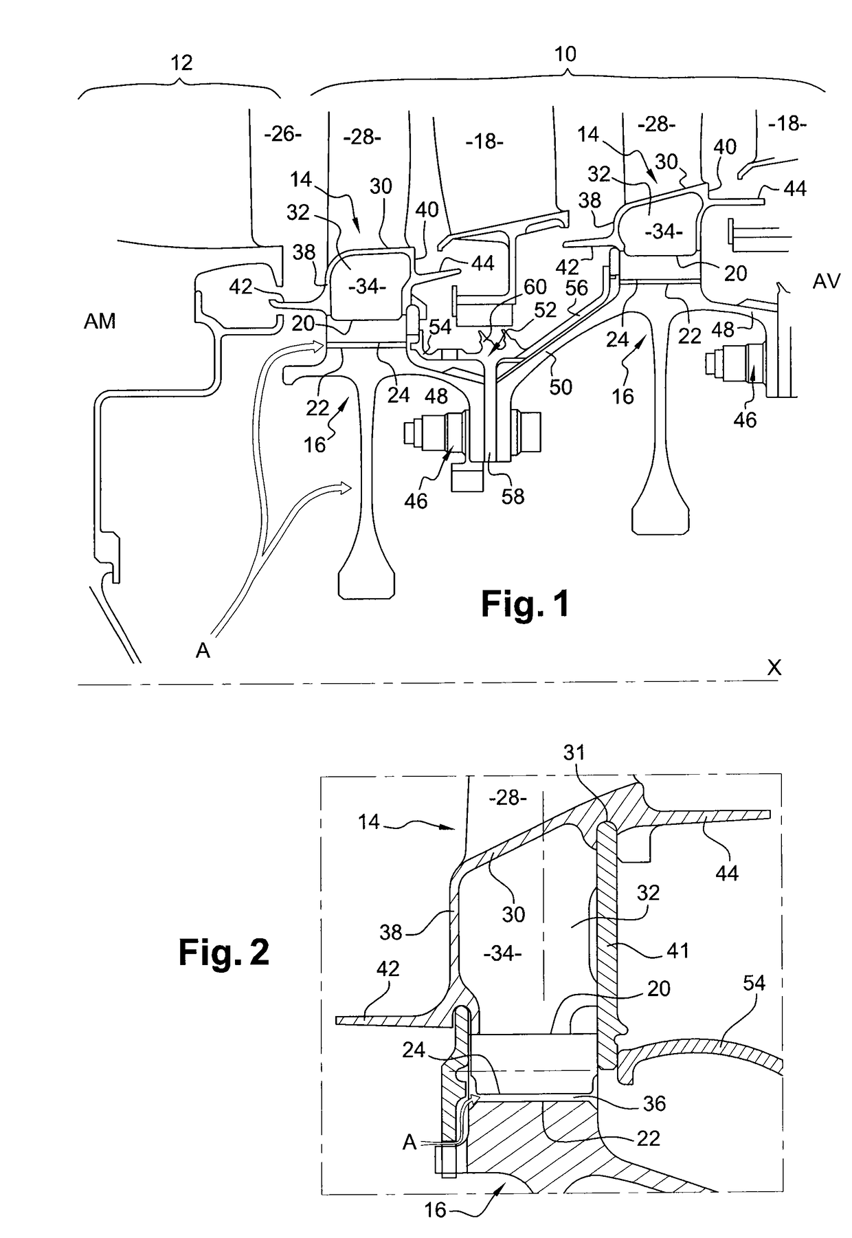
[0050]Each disc 16 comprises, on the external periphery of the teeth (the peak of which bears reference number 20) alternating with recesses (the bottom of which bears reference number 22) wherein blade roots (the internal end of which bears reference...


PUM


Abstract

A rotating assembly for a turbomachine, including a disc having an external periphery with alternating recesses and teeth, blades extending radially from the disc and the feet of which are axially engaged and radially retained in the recesses of the disc, platforms extending on the circumference from the blades and being arranged end to end on the circumference, with respect to each other, axial sealing device upstream and/or downstream of an annular zone extending radially from the platforms up to the disc. The sealing device radially includes an internal annular portion and an external annular portion structurally distinct from each other, and the external annular portion of which is elastically constrained radially inwards by the internal annular portion.

Description

BACKGROUND OF THE INVENTION[0001]Field of the Invention[0002]The invention relates to a rotating assembly for a turbomachine, such as, more particularly, a turbojet engine in a plane, as well as a turbomachine comprising such an assembly.[0003]Discussion of the Background[0004]Such an assembly, which can be found, in particular, in a turbine, comprises a disc, and blades extending radially outwards from the disc and the feet of which are axially engaged and retained radially in of the recesses of the external periphery of the disc, said recesses alternating with teeth of the disc. The blades also comprise internal platforms arranged end to end on the circumference, so as to define together the internal limit of the flow of hot gas circulating in the turbine. The portion of the blade located inside relative to the jet, i.e. between the internal platform and the root, is called a tang. According to such positioning, spaces are formed between two adjacent tangs, and form inter-tang or ...

Claims


Application Information

Patent Timeline
IPC IPC(8): F01D5/02F01D5/30F01D11/00F01D5/22
CPCF01D11/006F01D5/02F01D5/225F01D5/3015F01D5/3084F01D11/003Y02T50/672F05D2220/30F05D2240/55F05D2260/231F05D2260/30Y02T50/60
Inventor BLANCHARD, STEPHANE PIERRE GUILLAUMEITO-LARDEAU, YOUKI OLIVIER
Owner SN DETUDE & DE CONSTR DE MOTEURS DAVIATION S N E C M A
Why Eureka
Try Eureka