Turbine engine blade preform

Active Publication Date: 2017-12-05
SN DETUDE & DE CONSTR DE MOTEURS DAVIATION S N E C M A
View PDF11 Cites 1 Cited by
  • Summary
  • Abstract
  • Description
  • Claims
  • Application Information

AI Technical Summary

Benefits of technology

[0008]The present invention provides a simple, ef

Problems solved by technology

However, when the liquid material flows into the mold, the mold throat areas slow down the flow of material at these locations, which may lead to interrupted solidification and cold lap

Method used


Image

  • Turbine engine blade preform
  • Turbine engine blade preform
  • Turbine engine blade preform

Examples


Example

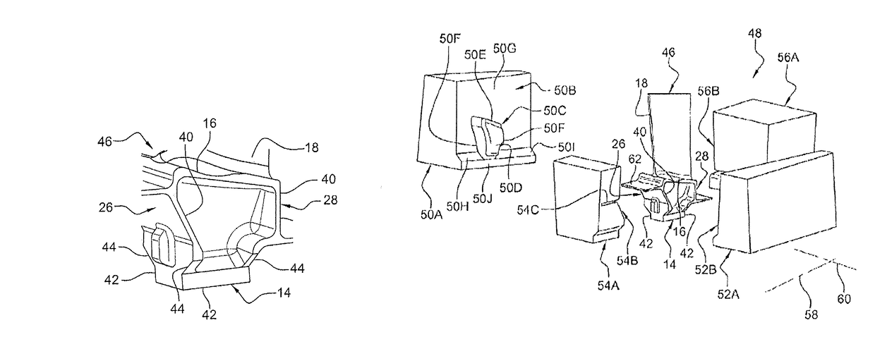
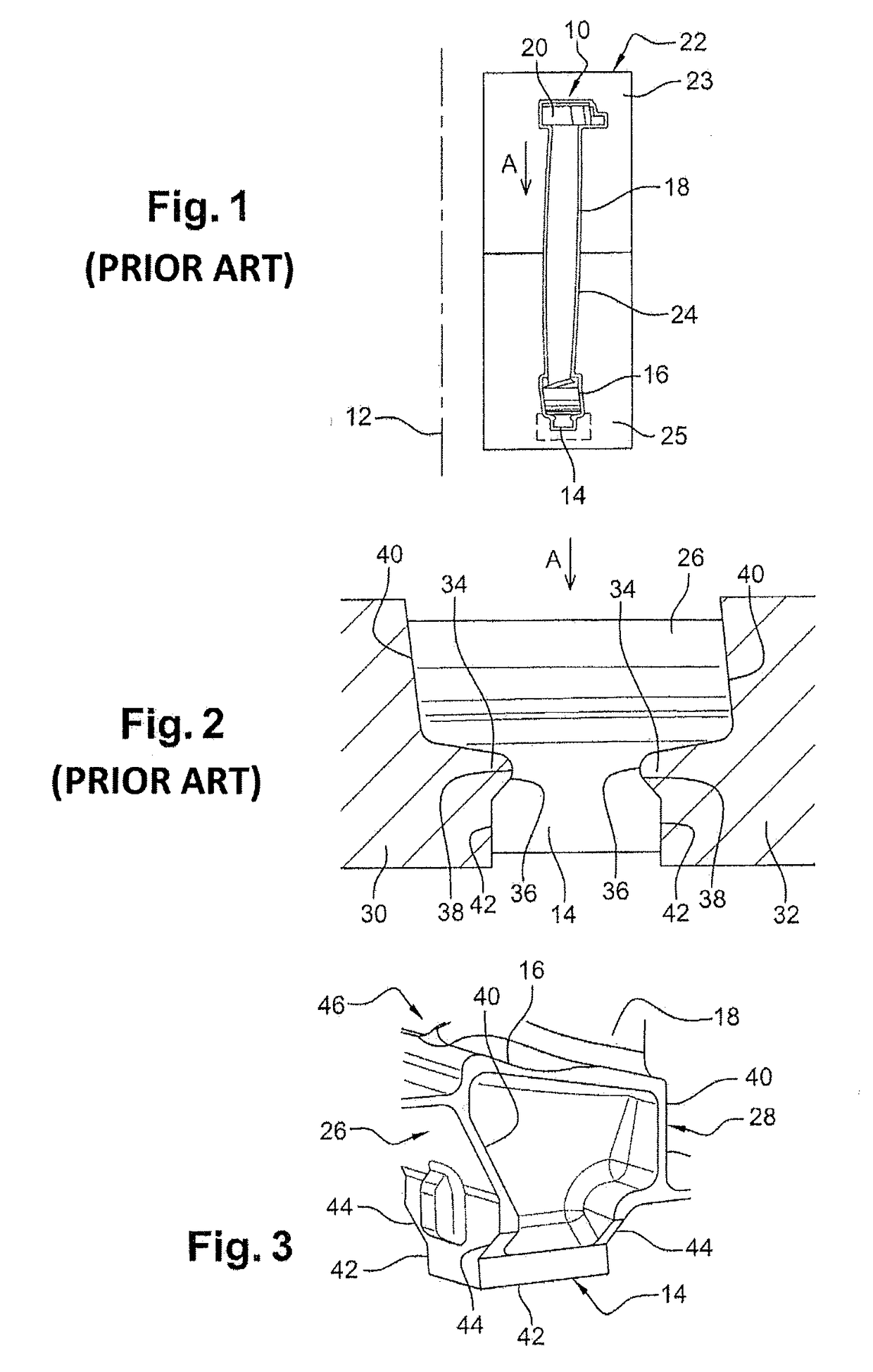
[0027]Reference will first be made to FIG. 1 which shows a one-piece turbine engine blade preform 10 according to the prior art obtained by molding in a mold and comprising, along the axis 12, a portion of the blade root 14 which extends longitudinally in an upstream / downstream direction and having, in cross-section, a substantially rectangular shape, a plat-form 16, a blade 18 and a blade root 20. From upstream or downstream, the outline of the root is U-shaped, with the branches of the U being substantially parallel and being formed by the flanks 42 of the blade root. The blade shown in FIG. 1 more particularly represents a blade mounted in a turbine of the turbine engine.

[0028]The mold 22 comprises an internal cavity 24, the three-dimensional shape of which is so determined that the desired three-dimensional shape of the blade preform 10 is obtained by filling the mold with the liquid material. In practice, the liquid material is injected into the mold 22 from a lower portion 23 ...


PUM

PropertyMeasurementUnit
Timeaaaaaaaaaa
Angleaaaaaaaaaa
Distanceaaaaaaaaaa

Abstract

A blade preform includes a strut connecting a plat-form to a blade root portion extending longitudinally in an upstream-downstream direction, an upstream web and a downstream web, which each extend in a direction substantially perpendicular to the longitudinal direction of the blade root and are formed at the upstream and downstream ends of the strut. The upstream and downstream webs connect the upstream and downstream ends of the plat-form to the upstream and downstream ends of the blade root. The blade root extends in a direction perpendicular to the longitudinal direction of the blade root over a distance smaller than that of the upstream and downstream webs and the side edges of each web are extended by walls that converge at the flanks of the blade root.

Description

CROSS-REFERENCE TO RELATED APPLICATIONS[0001]This application is a national stage of International Application No. PCT / FR2014 / 051324, filed on Jun. 4, 2014, which claims the benefit of French Patent Application 1355177, filed Jun. 5, 2013, the contents of each of which are incorporated herein by reference.BACKGROUND OF THE INVENTION[0002]The invention relates to a turbine engine blade preform, such as in particular a turbine blade preform in a turbine engine, and a mold and a method for obtaining the blade preform.[0003]In the current technique, the turbine blades are one-piece parts obtained by molding, using a mold comprising a cavity, the three-dimensional shape of which makes it possible to obtain the desired shape in a form-fitting manner. In practice, the part obtained after the step of molding consists of a blade preform which has to be machined to reach the desired final shape and dimensions.[0004]Thus, a turbine blade preform comprises a strut connecting a blade root to a p...

Claims


Application Information

Patent Timeline
IPC IPC(8): B22C9/06F01D5/14B22C9/10B22C9/22B22D25/02
CPCB22C9/10B22C9/06B22C9/22F01D5/141B22D25/02F05D2230/61F05D2230/21
Inventor CONGRATEL, SEBASTIEN SERGE FRANCISDUPEYRE, RAPHAEL JEAN PHILIPPEKLEIN, GUILLAUMEMATHIEU, DAVIDTANG, BA-PHUC
Owner SN DETUDE & DE CONSTR DE MOTEURS DAVIATION S N E C M A
Why Eureka
Try Eureka