
Voltage regulator for lnb
A technology of voltage regulators and devices, which is applied in the direction of instruments, electric variable adjustment, control/regulation systems, etc., and can solve problems such as high temperature of components, high cost, noise, etc.
Patent Information
- Authority / Receiving Office
- CN · China
- Patent Type
- Applications(China)
- Current Assignee / Owner
- Publication Date
- 2010-06-09
- Estimated Expiration
- Not applicable · inactive patent
Smart Images
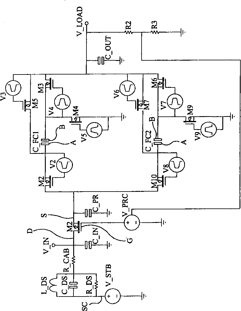
Figure 1 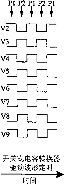
Figure 2 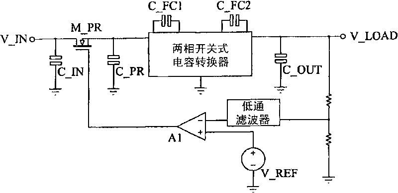
Figure 3
Abstract
Description
technical field
[0001] The present invention relates to a voltage regulator, in particular but not exclusively to a voltage regulator suitable for an LNB comprising more than one low noise amplifier. Background technique
[0002] A low-noise block (or LNB) is a well-known device, also known as a down converter, due to its ability to convert an entire frequency band or block of frequencies to a lower frequency band. The LNB is usually incorporated into the satellite signal receiving device or dish wire and is placed at the end of the arm so that it is aligned with the parabolic reflective dish wire so that the parabolic reflective dish wire can reflect the signal received from the antenna Focus on the feed horn of the LNB. The LNB converts the received signal to a lower frequency band, and then uses a connecting cable (usually coaxial cable) to send the low frequency signal to the satellite receiver.
[0003] Satellite LNBs typically use amplifiers and controllers that oper...
Examples
Embodiment Construction
[0042] Refer below figure 1 , figure 1The core elements of an embodiment of the invention in a single general purpose LNB (single output device) are shown. The voltage source Vstb represents the set-top box, which not only supplies power to the LNB, but also receives RF signals from the LNB. Lds, Cds, and Rds represent the DiSEqC filter network, which allows the 22kHz control signal to be fed into the power line. A negative effect of this network is that it increases the low-frequency impedance of the power line, making it easier to interfere with noisy loads. The supply Vprc and the FET it drives (M_PR) function as a pre-regulator (ie they form part of the regulation arrangement). The adjustment device can also be described by a linear adjustment device. The linear preregulator is followed by a two-phase switched capacitor DC / DC converter. Phase 1 uses pulse generators V2, V3, V4, and V5 and the FETs driven by them. Phase 2 uses pulse generators V6, V7, V8 and V9 and th...