
Self-excited Buck circuit
A self-excited, circuit technology, used in electrical components, adjusting electrical variables, instruments, etc., can solve problems such as insufficient output voltage stability, achieve good adjustment rate, reduce the number of coupled inductor turns, and achieve the effect of protection
Patent Information
- Authority / Receiving Office
- CN · China
- Patent Type
- Patents(China)
- Current Assignee / Owner
- Publication Date
- 2014-11-19
Smart Images
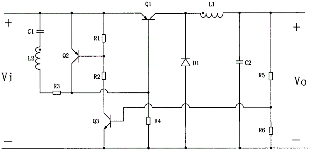
Figure 1 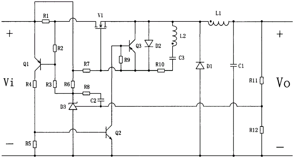
Figure 2 
Figure 3
Abstract
Description
technical field
[0001] The invention relates to a self-excited Buck circuit. Background technique
[0002] In small and medium power applications, compared with other excited DC / DC converters and linear voltage regulator circuits, self-excited DC / DC converters have the advantages of simple circuit, fewer components, high efficiency and low cost.
[0003] At present, the main switching tube of the self-excited Buck converter is generally implemented by a bipolar transistor; the switching tube is controlled by adding an auxiliary winding to the output filter inductor; by comparing the signal after sampling the output voltage with the voltage Vbe of the triode, The turn-off control of the switching tube is realized through a certain circuit, and then the purpose of stabilizing the output voltage is achieved.
[0004] Chinese Patent No. ZL99108088.2 discloses a self-excited Buck converter circuit, such as figure 1 shown. Vi and Vo are the DC input and output voltages of the c...
Examples
Embodiment Construction
[0022] The specific embodiments of the present invention will be further introduced below in conjunction with the accompanying drawings.
[0023] Such as figure 2 As shown, the present invention is the self-excited Buck conversion circuit, including: inductor L1, capacitor C1, diode D1, switch tube V1 and output sampling resistors R11, R12, and also includes current sampling resistor R1, PNP transistor Q1, PI Regulating circuit, self-excited drive circuit. The PI regulation circuit includes a reference regulator D3, a capacitor C2 and resistors R6 and R8. The self-excited drive circuit includes a coupling inductor L2, a capacitor C3, and a resistor R10.
[0024] In the circuit, Vi and Vo are the input and output voltages of the converter respectively. Inductor L1, capacitor C1, diode D1, and switch tube V1 constitute the Buck main circuit. In the Buck main circuit, the current sampling resistor R1 is connected in series with the Buck main circuit. Among them, one end of ...