

Boiler capable of adjusting flue gas temperature of furnace outlet
A furnace outlet, flue gas temperature technology, applied in the combustion of block fuel and liquid fuel, the combustion of block fuel and gaseous fuel, the combustion of block fuel and powder fuel, etc., can solve the effect of boiler economy Larger problems, to achieve the effects of strong adaptability and adjustability, increasing dust area, and simple transformation methods
Patent Information
- Authority / Receiving Office
- CN · China
- Patent Type
- Applications(China)
- Current Assignee / Owner
- Publication Date
- 2012-11-21
- Estimated Expiration
- Not applicable · inactive patent
Smart Images
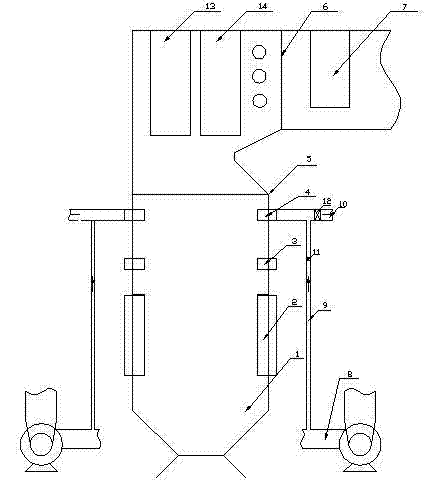
Figure 1
Abstract
Description
technical field
[0001] The invention relates to a boiler capable of adjusting the flue temperature at the outlet of a furnace. Background technique
[0002] In recent years, due to the rapid development of thermal power and the tight supply of thermal coal, it is impossible to guarantee that power generation boilers will use the designed coal or close to the designed coal. Xinjiang Zhundong has a large coal output, and many power plants are forced to use the coal produced in this area due to the shortage of fuel supply. The content of Na and Cl elements in Zhundong coal is high, and the Na 2 The O content can reach 4%, and the Cl element compound content can reach 3%. The melting point of the compound formed by Na and Cl elements in the coal ash is low. Due to this feature, the coal ash is brought to the superheater tube with the hot flue gas and deposited after cooling. Contamination and coking are generated, which then block the high-temperature superheater, block the air...
Examples
Embodiment
[0011] Example: such as figure 1 As shown, the boiler capable of adjusting the flue temperature at the furnace outlet includes a furnace 1, a furnace outlet 6 connected to the upper port of the furnace 1, a front screen superheater 13 installed in the furnace outlet 6, a rear screen superheater 14 and a high-temperature superheater 7 . Below the lower edge 5 of the flame angle in the furnace 1, namely the four corners of the middle part of the furnace 1, a burner group 2 is installed, and a remote type overburning air spout 3 is installed above the burner group 2, or the overburning air spout 3 may not be installed. At the four corners of the furnace 1 more than two meters above the type burn-off air spout 3, a temperature-regulating air spout 4 is installed. The height of the temperature-regulating air spout 4 is lower than the lower edge 5 of the refraction angle, and the lower edge 5 of the refraction angle is a known technology, and its specific position will not be descr...
Embodiment 2
[0014] Embodiment 2: as figure 1 As shown, another technical means of the present invention: arrange the tempering air nozzle 4 at the position before the furnace outlet 6, that is, between the rear panel superheater 14 and the high temperature superheater 7. At the same time, guide vanes are installed in the temperature-regulating air spout 4, and the guide vanes can rotate the air flow to strengthen the mixing with the flue gas. The guide vanes are in the form of typical swirl burners or oil burners. All the other are the same as in Example 1.
Embodiment 3
[0015] Embodiment 3: as figure 1 As shown, another technical means of the present invention: the temperature-regulating air nozzle 4 is arranged on the four furnace walls of the furnace 1 close to the lower edge of the refraction angle or two of them on the opposite furnace walls. All the other are the same as in Example 1.