

Solid electrolytic capacitor and manufacturing method thereof
A technology of solid electrolysis and capacitors, which is applied in the direction of solid electrolytic capacitors, electrolytic capacitors, capacitors, etc., and can solve problems such as increased leakage current and deterioration of dielectric films
Patent Information
- Authority / Receiving Office
- CN · China
- Patent Type
- Applications(China)
- Current Assignee / Owner
- Publication Date
- 2014-12-03
- Estimated Expiration
- Not applicable · inactive patent
Smart Images
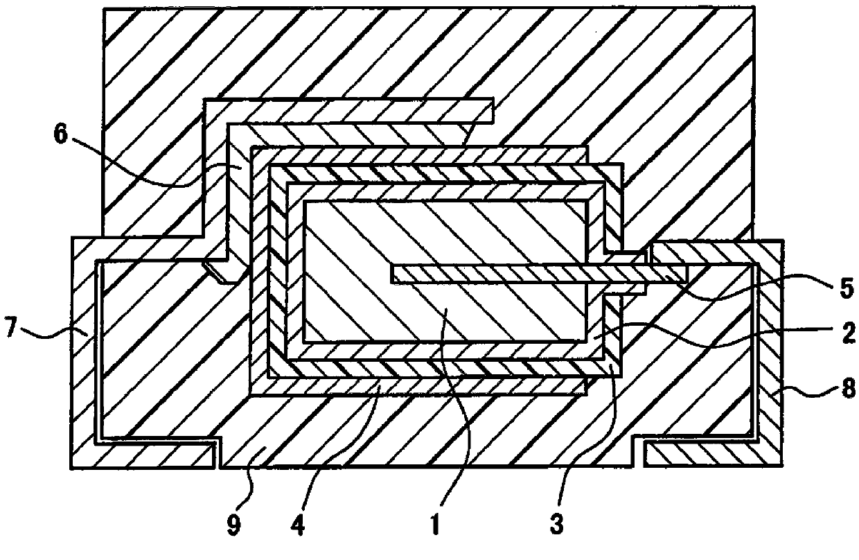
Figure 1 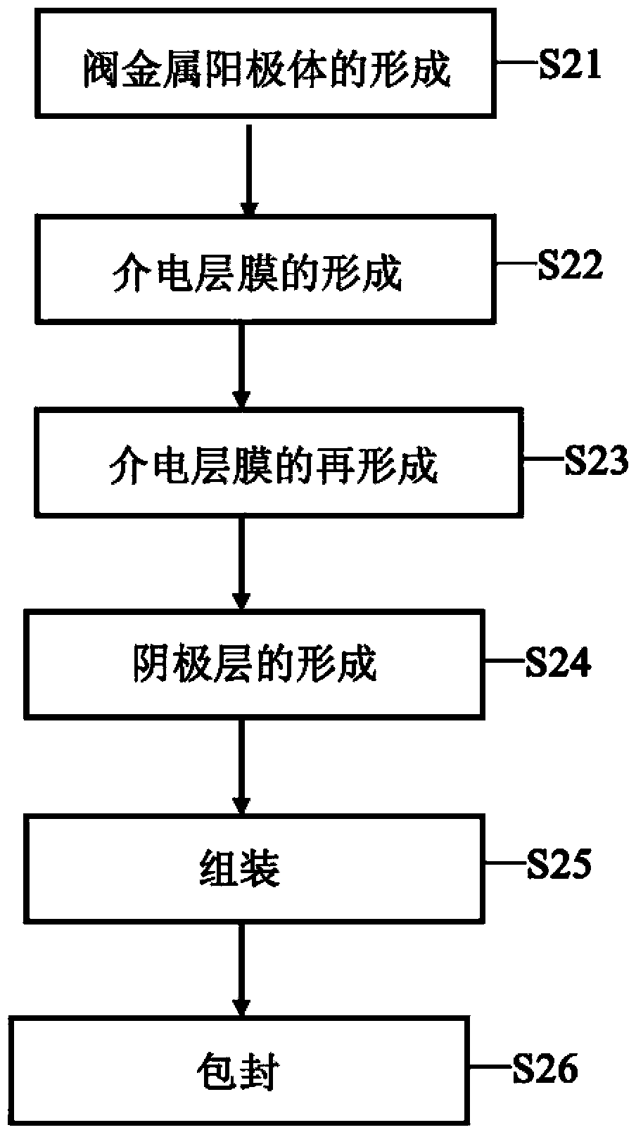
Figure 2 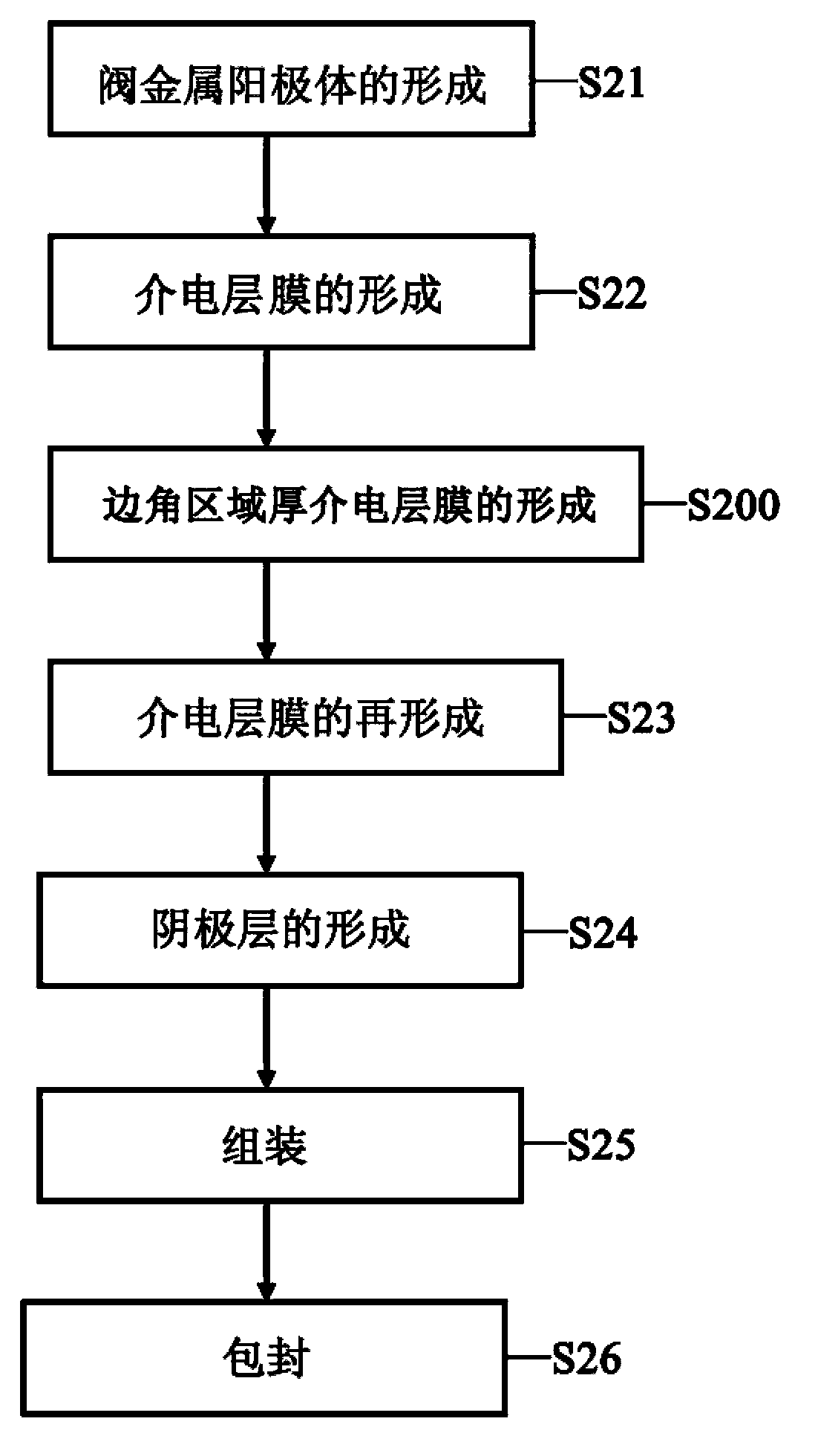
Figure 3
Abstract
Description
technical field
[0001] The invention relates to a solid electrolytic capacitor and a manufacturing method thereof, in particular to a solid electrolytic capacitor with a thick dielectric layer in the corner area and a manufacturing method thereof. Background technique
[0002] The basic construction of solid electrolytic capacitors, such as figure 1 shown. Usually, it is formed on a valve metal anode body 1 (as long as it is a molded body with pores) including a valve metal foil anode body with an enlarged specific surface area through corrosion treatment or a valve metal powder sintered body with pores. An oxide thin film is used as the dielectric layer film 2. The valve metal is usually tantalum, niobium, aluminum, titanium and other metals and alloys or oxides thereof. The dielectric layer film 2 formed on the surface of the valve metal anode body 1 is usually formed by electrolytic oxidation treatment; a solid electrolyte layer 3 is formed on the outside of the dielec...
Examples
preparation example Construction
[0051] The preparation methods of conductive polymers usually include chemical oxidative polymerization and electrolytic oxidative polymerization: on the dielectric layer film 2, organic polymer monomers and oxidant (including dopant) solutions are attached separately or simultaneously, and then on the dielectric layer film 2 The process of polymerizing to form a conductive polymer is called chemical oxidation polymerization; the valve metal anode body containing a conductive polymer seed layer generated by chemical oxidation is immersed in an electrolyte containing organic polymer monomers and dopants, and the electrolytic oxidation The polymerization voltage is applied between the auxiliary electrode in contact with the conductive polymer seed layer and the cathode plate placed in the electrolyte alone, and the process of continuing to grow the conductive polymer on the conductive polymer seed layer of the valve metal anode body is called Electrolytic Oxidative Polymerization...
example 1
[0081]Weld the 3.5mm wide and 9.8mm long chemically formed aluminum foil anode body to the metal craft bar, and divide the aluminum foil anode body into two parts of 4mm and 5mm with polyimide with a width of 0.8mm after curing (playing the role of shielding lines) , the 3.5mmx4mm part of the aluminum foil anode body is anodized at 50°C with a mass percent of 8% ammonium adipate aqueous solution for 30 minutes (dielectric layer film formation process), which can form mainly Al2O3 dielectric layer film. Next, protect the aluminum foil anode body with the protective material polypropylene to ensure that the front and rear surfaces except the corner area are protected by the protection material, and immerse the protected aluminum foil anode body into a 0.05% by mass percentage of ammonium acetate aqueous solution 12V electrolytic oxidation voltage was applied and the voltage was kept constant for 5 minutes (the process of forming a thick dielectric film in the corner area). Afte...
example 2
[0095] The aluminum foil anode bodies are tightly wound together, and the upper and lower surfaces of a certain layer of aluminum foil anode bodies are protected by the lower and upper surfaces of the adjacent aluminum foil anode bodies, and the outermost layer of the winding body is protected by polypropylene For material protection, immerse the protected aluminum foil anode coil in 0.05% by mass ammonium acetate aqueous solution, apply an electrolytic oxidation voltage of 88V and keep the voltage constant for 5 minutes (the process of forming a thick dielectric film in the corner area). Then, the 3.5mm wide and 9.8mm long aluminum foil anode body is welded to the metal craft bar, and the aluminum foil anode body is divided into two parts of 4mm and 5mm with polyimide with a width of 0.8mm after curing. The 3.5mmx4mm part is anodized at 50°C and 8% by mass of ammonium adipate aqueous solution, applying a voltage of 11V for 30 minutes, so that a dielectric layer film (dielectri...