
A self-catalytic denitrification system for sintering dust coupled with waste heat of sintering dust
A technology of self-catalysis and soot, which is applied in the direction of chemical instruments and methods, separation methods, and separation of dispersed particles, can solve the problems of low equipment investment and operating costs, difficult disposal of waste catalysts, and high operating costs, and achieve equipment investment and operating costs Low cost, reduced investment in denitrification equipment, and full use of waste heat in the system
Patent Information
- Authority / Receiving Office
- CN · China
- Patent Type
- Patents(China)
- Current Assignee / Owner
- Publication Date
- 2020-06-02
Smart Images
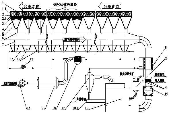
Figure 1
Abstract
Description
technical field
[0001] The invention relates to a flue gas denitrification process in the field of environmental protection, in particular to a sintering fume autocatalytic denitrification system which couples and utilizes the waste heat of sintering fume. Background technique
[0002] Sintering flue gas is a gas containing a variety of polluting components produced during the ignition, melting, and high-temperature sintering of various powdery iron-containing raw materials, fuels, and fluxes. The sintering flue gas has a large amount of flue gas (4000-6000m 3 / ton of sinter), large temperature changes (120-200°C), high CO concentration (0.5-2.0%), SO 2 Concentration changes greatly (1000-3000mg / Nm 3 ), NO x Low concentration (300-500 mg / Nm 3 ), high moisture content (7-12%) and high oxygen content (15-18%). Compared with power plant flue gas, it has many characteristics of its own, its flue gas composition is more complex, its changes fluctuate more, and its treatment...
Examples
Embodiment Construction
[0028] The system of the present invention will be further explained below in conjunction with the accompanying drawings:
[0029] The bottom of the trolley 1.1 of the sintering machine 1 is provided with a bellows 5, the outlet at the bottom of the bellows 5 is connected to the main flue 7, and the sintering machine 1 is sequentially divided into an ignition section, a head section, a flue gas rapid heating section and a There are 4 areas in the tail section, the ignition section is located at the front end of the sintering machine 1, and this area occupies 1-2 bellows length; the nose section is located in the front half of the sintering machine after the ignition section and extends to the middle of the sintering machine. The area accounts for 35-45% of the total length of the sintering machine; the rapid heating section of the flue gas is located in the middle of the sintering machine towards the tail of the machine, and this area occupies 2-4 lengths of the bellows; the ta...