
Heat collecting device for collecting heat of disc type or tower type solar reflector
A technology of tower-type solar energy and reflectors, which is applied to the components of solar collectors, solar thermal energy, and solar thermal power generation. And other problems, to achieve the effect of wide range of heating medium, simple structure, and short construction period
Patent Information
- Authority / Receiving Office
- CN · China
- Patent Type
- Applications(China)
- Current Assignee / Owner
- Publication Date
- 2018-08-07
- Estimated Expiration
- Not applicable · inactive patent
Smart Images
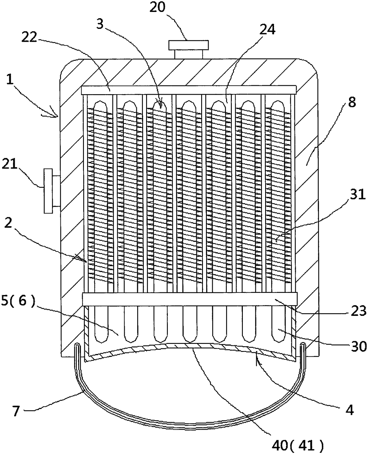
Figure 1 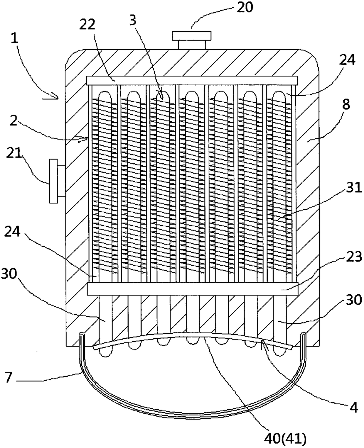
Figure 2 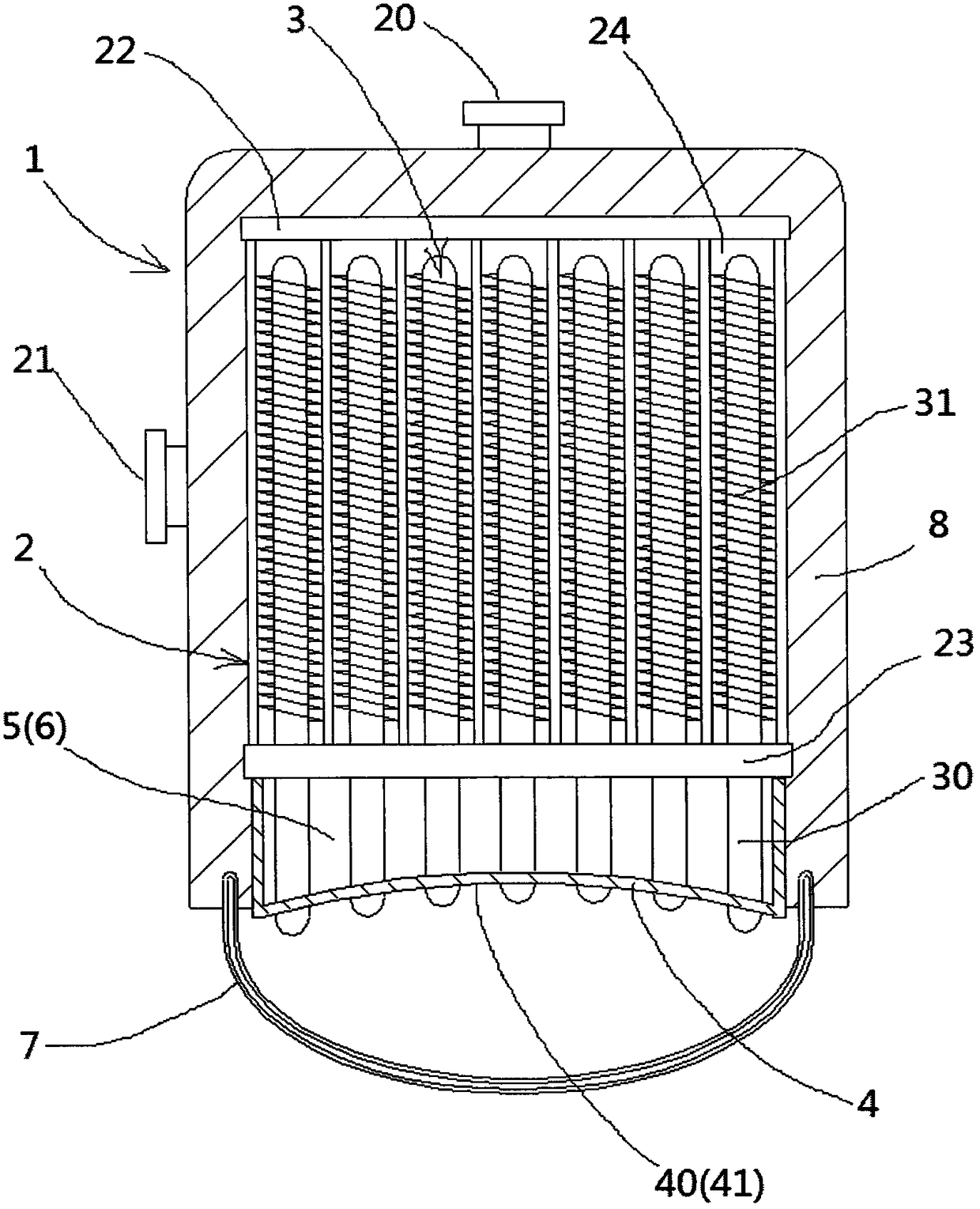
Figure 3
Abstract
Description
technical field
[0001] The invention belongs to the technical field of solar heat utilization, and in particular relates to a technology of a heat collecting device used for dish or tower solar reflectors to collect heat. Background technique
[0002] On the one hand, the level of human energy consumption continues to increase, on the other hand, conventional fossil energy is increasingly exhausted, and the pollutant emissions associated with conventional fossil energy are increasingly unable to meet people's demand for future energy. Solar energy, as an inexhaustible new clean energy, is getting more and more attention, and the development of solar energy is making progress day by day.
[0003] Currently popular solar power generation is mainly divided into two forms: photovoltaic power generation and solar thermal power generation. Among them, photovoltaic power generation uses solar panels or battery thin films to receive sunlight and directly convert light energy into e...
Examples
Embodiment 1
[0039] Such as figure 1 with Figure 4 As shown, a heat collecting device for dish or tower solar reflectors includes a heat collecting device 1, which is composed of a pressure-resistant heat exchange cavity 2, a heat pipe 3, and a light collecting head 4.
[0040] The pressure heat exchange cavity 2 is provided with a fluid outlet 20 and a fluid inlet 21. The pressure heat exchange cavity 2 is rolled into a single spiral flow channel by a steel plate, and welded at both ends of the single spiral flow channel. After the upper cover plate 22 and the lower cover plate 23, a single helical channel 24 is formed through which fluid can pass. One end of the single helical channel 24 is connected to the fluid outlet 20, and the other end is connected to the fluid inlet 21. .
[0041] The heat pipe 3 includes a heat absorption section 30 (or an evaporation section) and a heat dissipation section 31 (or a condensation section). Then, through the lower cover plate 23 , heat conducti...
Embodiment 2
[0045] Such as Figure 4 As shown, the heat transfer medium 6 filled in the housing cavity 5 is fine copper powder or nano silicon carbide or nano high temperature resistant alloy powder. For others, refer to Embodiment 1, which will not be repeated here.