
Ductless ventilation method for underground water treatment structure
A ventilation method and water treatment technology, which is applied to drainage structures, buildings, waterway systems, etc., can solve the problems of many crossing conflicts of deodorizing pipes, difficulties in construction and hoisting, and large amount of installation and maintenance works, so as to reduce the operating capacity of the system The effect of reducing power consumption and fan operation noise, improving ventilation efficiency and sewage discharge efficiency, and reducing initial investment in civil engineering
Patent Information
- Authority / Receiving Office
- CN · China
- Patent Type
- Applications(China)
- Current Assignee / Owner
- Publication Date
- 2019-03-08
Smart Images
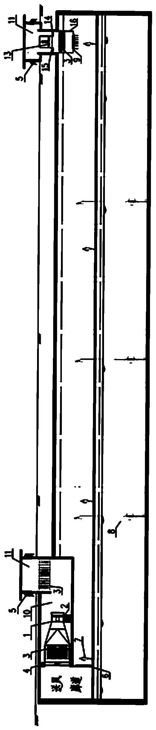
Figure 1 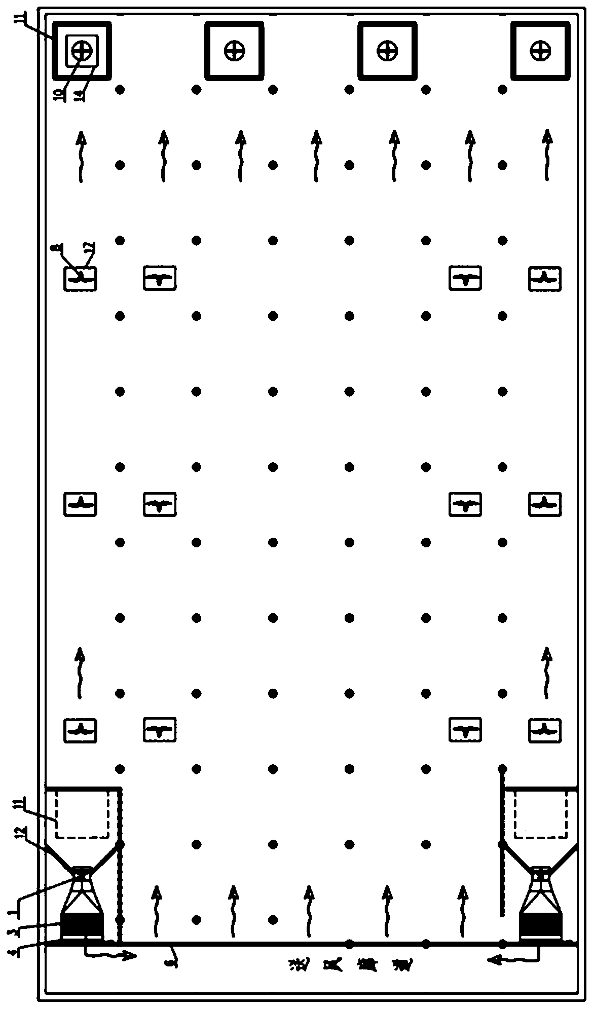
Figure 2 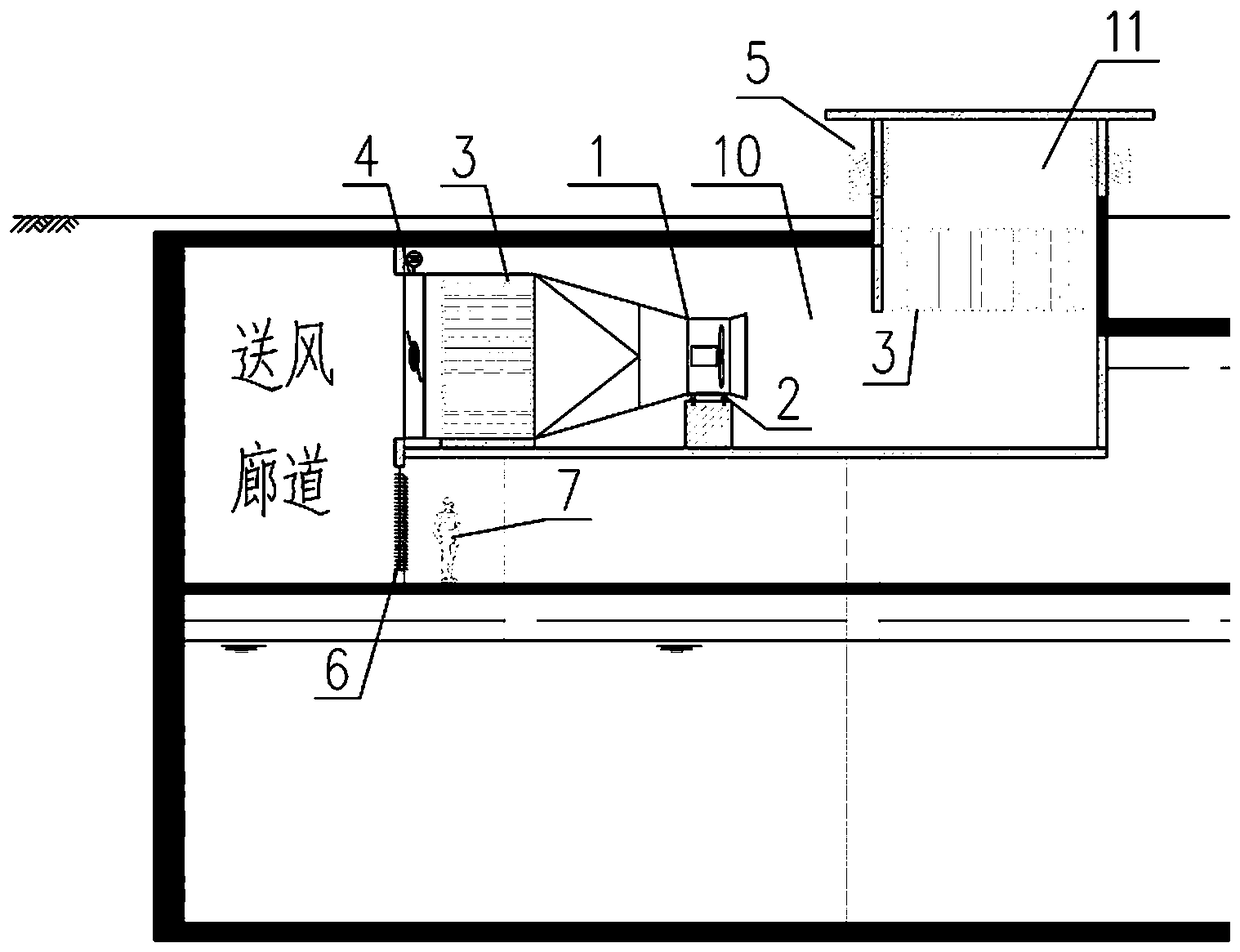
Figure 3
Abstract
Description
technical field
[0001] The invention relates to the field of water treatment, in particular to a ductless ventilation method suitable for underground water treatment structures. Background technique
[0002] The underground water treatment structure transfers the water treatment facilities from the open air to the underground. It has the advantages of strong sealing, environmental friendliness, small footprint, can improve the quality of surrounding plots, organically integrates with greening and water features, and has good aesthetics. Recognized by local governments and surrounding residents, the demand for construction has increased sharply, and it has become a new direction for urban water treatment engineering construction.
[0003] Underground water treatment structures are generally divided into three layers: the ground layer usually includes a number of ventilation shafts, entrances and exits, etc., and most of the rest are soil-covered greening; the basement layer i...
Examples
Embodiment
[0026] Embodiment: This embodiment specifically relates to a ductless ventilation system for underground water treatment structures, which has high ventilation efficiency and sewage discharge efficiency, low air age, less ventilation stagnation areas, and good uniformity of air supply and exhaust. With the advantages of low energy consumption and low noise, it can effectively reduce the overall buried depth of underground water treatment structures, reduce the pressure head of fans, and save initial investment in project construction and operation and maintenance costs such as image 3 As shown, the ductless ventilation system of an underground water treatment structure consists of an air intake unit, an air supply corridor, a ventilation target area, and an exhaust unit.
[0027] The air intake unit includes: air blower 1, spring shock absorber 2, array muffler 3, electric control valve 4, muffler and rainproof louvers 5, air intake channel 10, air well 11, deflector 12.
[0...