
Face sealing annular valve for a fluid-working machine
Patent Information
- Authority / Receiving Office
- US · United States
- Current Assignee / Owner
- Publication Date
- 2013-02-07
Smart Images
Figure 1 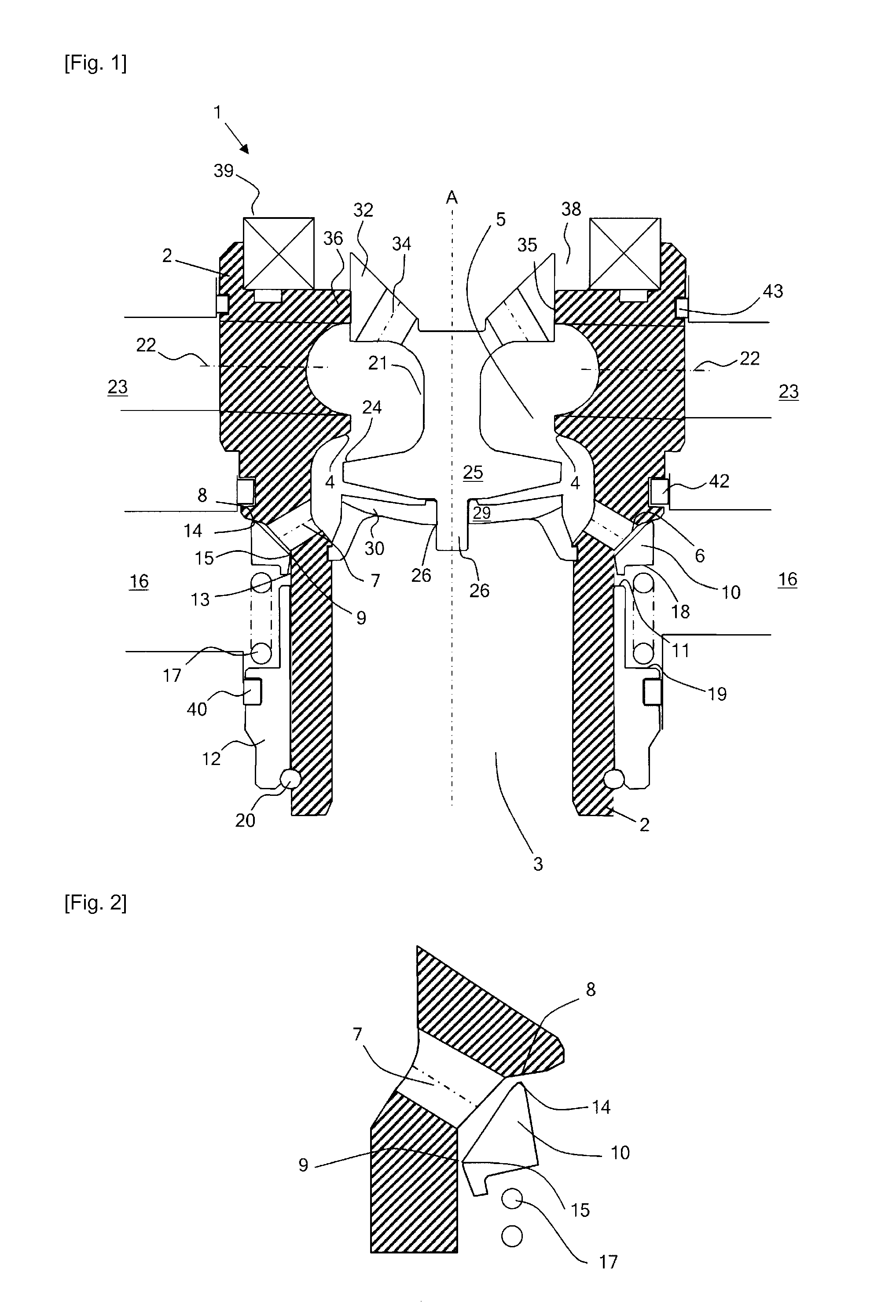
Figure 2 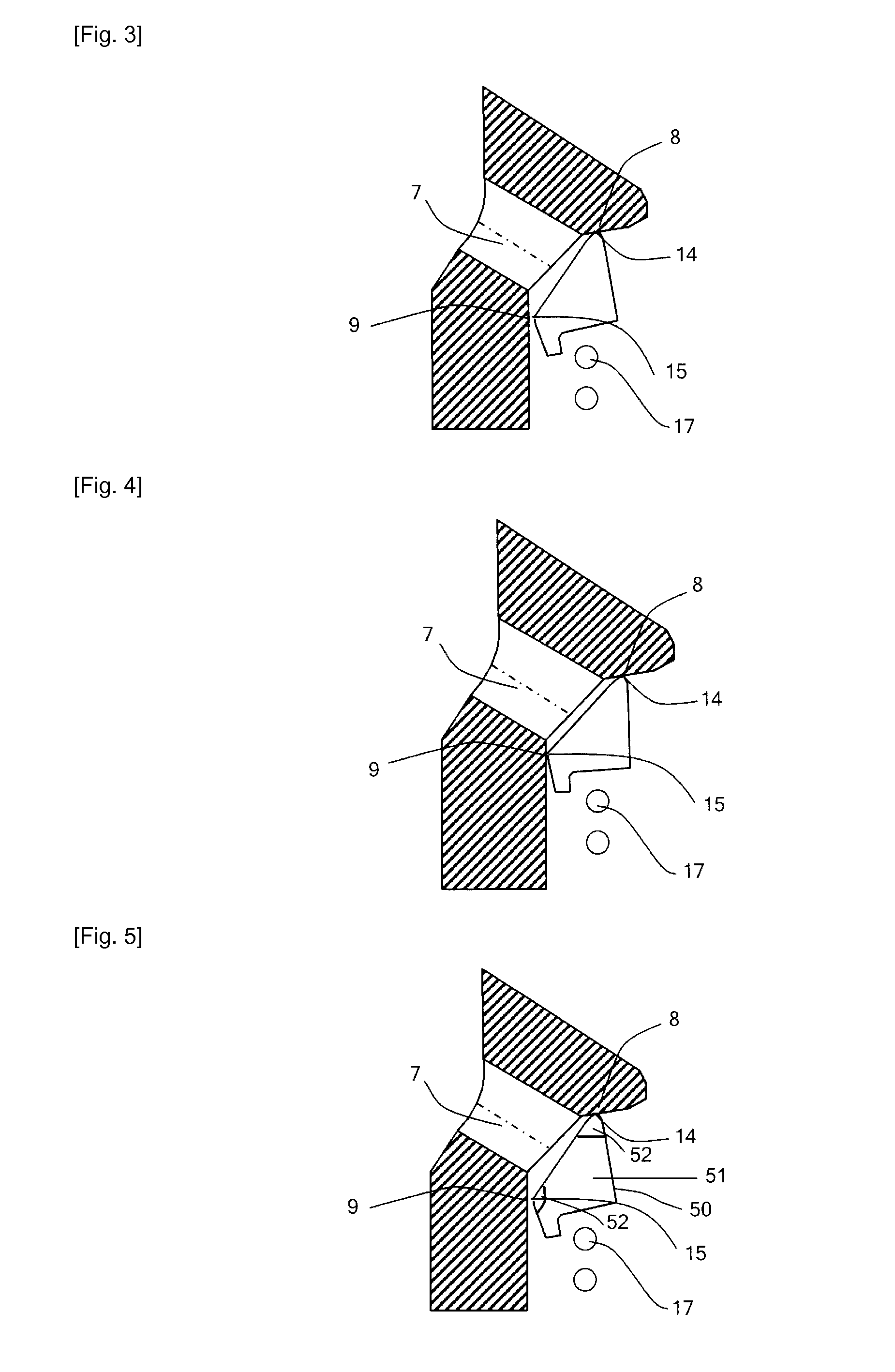
Figure 3
Abstract
Description
TECHNICAL FIELD
[0001] The invention relates to the field of face sealing annular valves suitable for use in fluid-working machines, such as hydraulic pumps, hydraulic motors and hydraulic pump-motors.BACKGROUND ART
[0002] It is known to use face sealing annular valves to regulate the flow of hydraulic fluid into or out of a piston cylinder, or other working chamber of a fluid-working machine. In annular valves of this type, a ring-shaped fluid path is selectively sealed by a similarly ring-shaped annular valve member. Annular valves are advantageous as they can provide a relatively large cross-sectional area through which hydraulic fluid can flow into or out of a working chamber.
[0003] It is desirable for face sealing annular valves to be relatively small, in order to reduce the diameter of, the annular valve and therefore the size of fluid-working machine. It is also desirable for annular valves to be formed from as few parts as possible, and with as large tolerances as possible, while...
Examples
second embodiment
[0090]For example, with reference to FIGS. 5 and 6, an annular valve member 50 has a resilient body 51 and a rigid coating 52, such as a graphite layer, at each of the first and second seat-engaging surfaces. The resilient body is elastically deformable to enable the annular valve member to deform between the relaxed configuration (FIG. 5) and deformed configuration (FIG. 6) although the rigid coating does not deform.
third embodiment
[0091]With reference to FIGS. 7 and 8, an annular valve member 60 has a rigid body 61, formed of steel, and sealing members 62, formed of PEEK or another resilient material, which defines the outer and inner seat-engaging surfaces. Thus, although the majority of the annular valve member 60 does not deform elastically, it remains the case that in a relaxed configuration, the outer seat-engaging surface can form a seal with the outer sealing surface of the annular valve seat but the inner seat-engaging surface does not sealedly engage with the inner sealing surface of the annular valve seat. However, the sealing members can deform sufficiently under pressure to enable both inner and outer seals to be formed.
fourth embodiment
[0092]FIGS. 9 and 10 illustrate an annular valve member 70 formed as a steel leaf spring which is curved in cross-section and is sufficiently thin to deform elastically. In a relaxed configuration shown in FIG. 8, the annular valve member has an outer portion 71 including an outer seat-engaging surface which can sealingly engage with the outer sealing surface of the annular valve seat, and an inner portion 72 which is too large for the inner seat-engaging surface to form a seal with the inner sealing surface. As before, the annular valve member is loosely retained around the outer surface of the cylinder in the relaxed configuration but fits tightly, forming a good seal, in the deformed configuration.
[0093]FIGS. 11 and 12 illustrate a fifth embodiment of an annular valve member 80 according to the invention. In the fifth embodiment, the annular valve member is formed from a resilient material, such as PEEK, and is suitable for sealing an annular valve in which the inner and outer se...