
Gas concentration sensor
Patent Information
- Authority / Receiving Office
- US · United States
- Current Assignee / Owner
- Publication Date
- 2001-10-30
- Estimated Expiration
- Not applicable · inactive patent
Smart Images
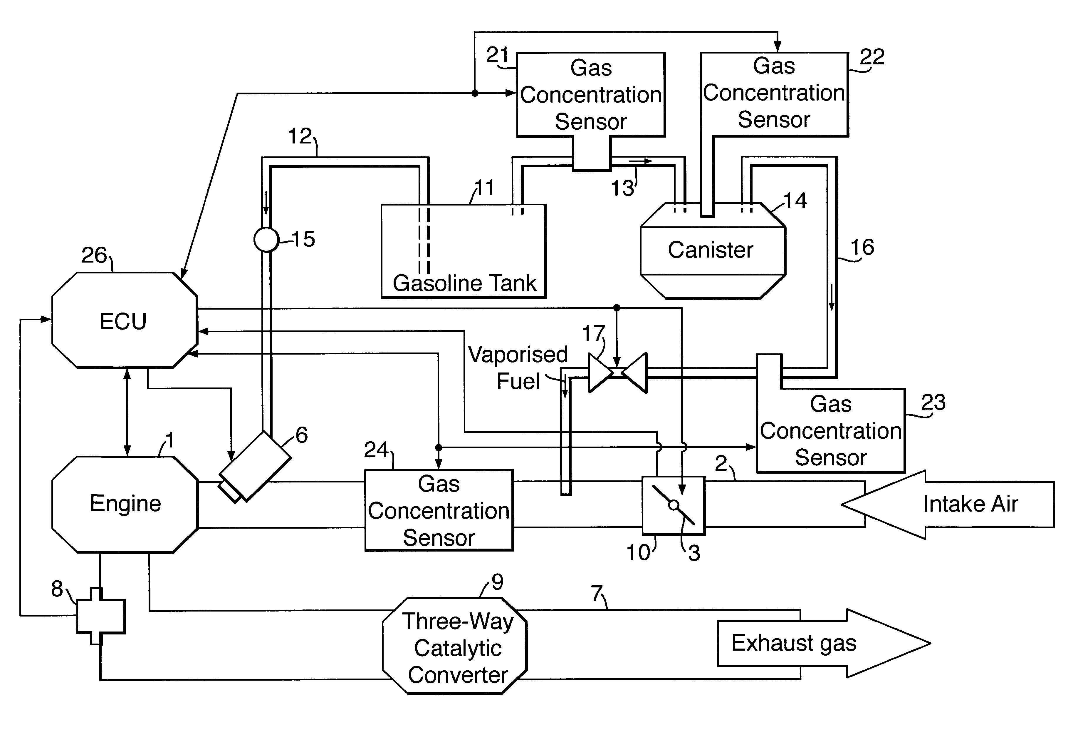
Figure 1 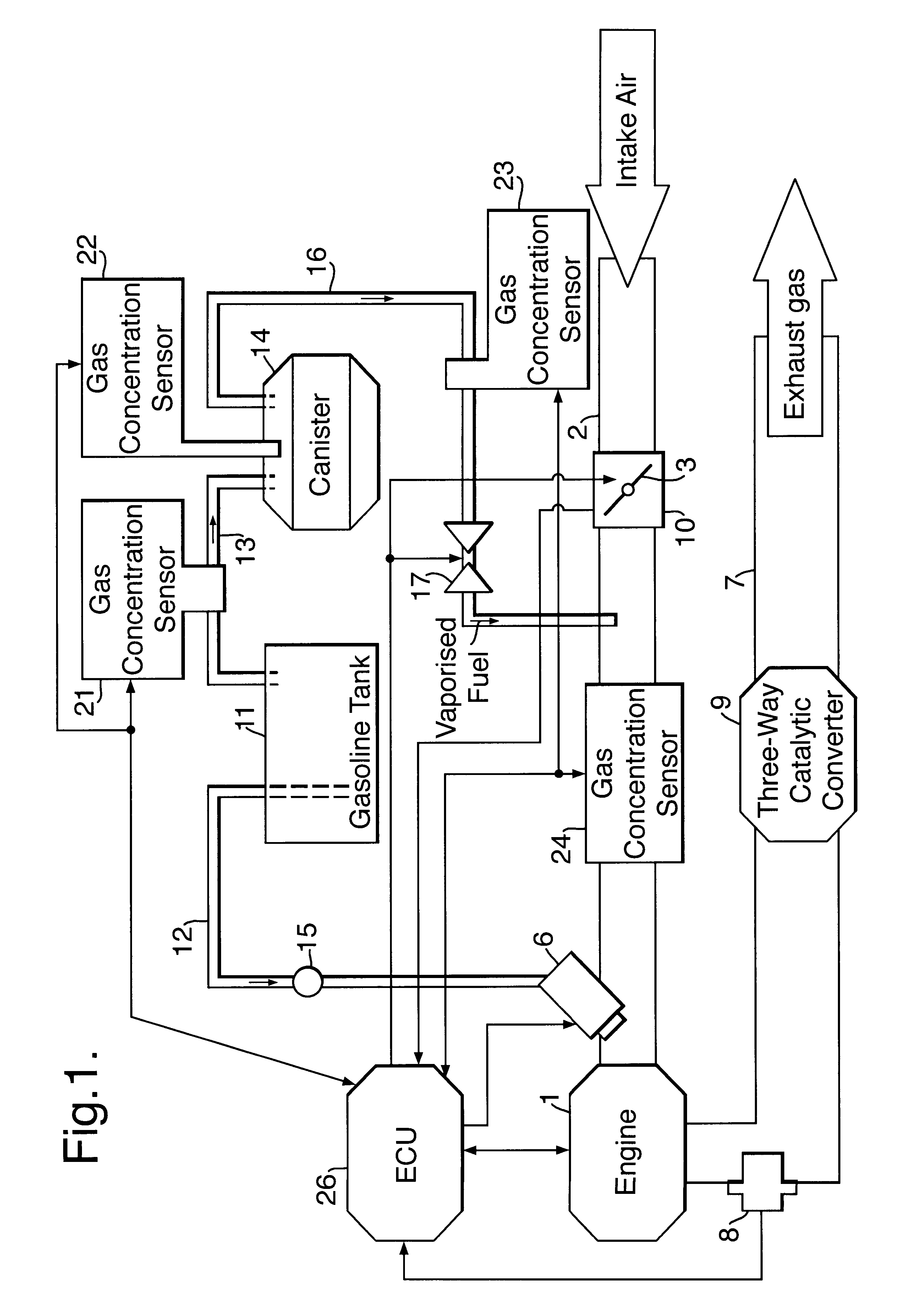
Figure 2 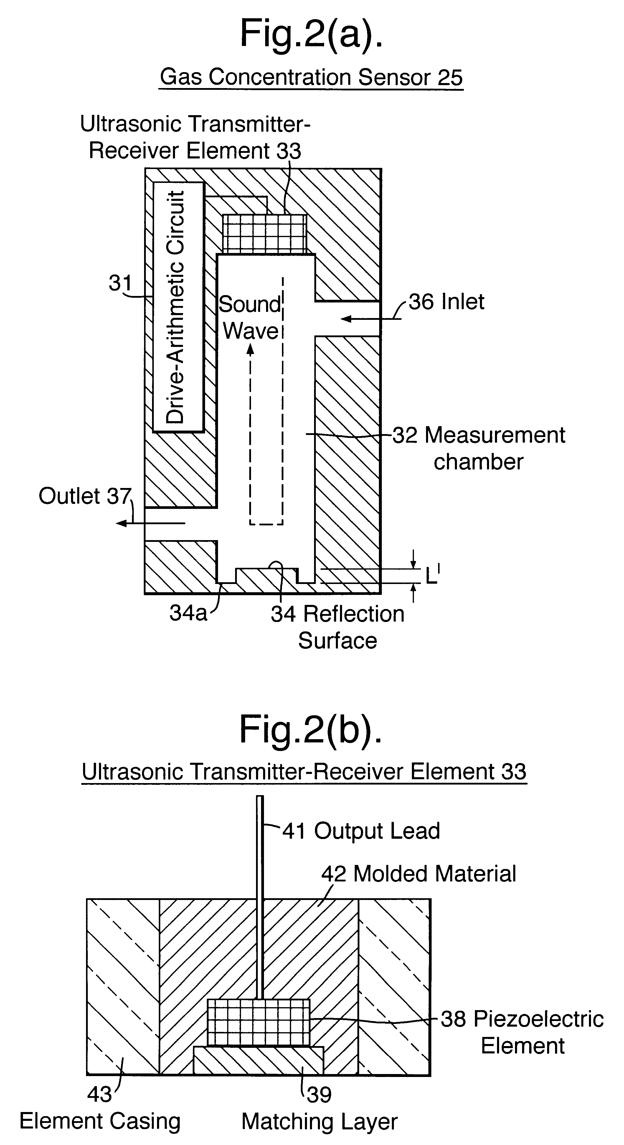
Figure 3
Abstract
Description
Field of the InventionThe present invention relates to a gas concentration sensor for measuring the concentration of combustible gas, such as vaporized fuel, contained in, for example, intake air to be supplied into an intake pipe of, for example, an internal combustion engine, or for measuring the concentration of a gas component in fuel gas of a fuel cell or in exhaust gas. 2. Description of the Related ArtConventionally, a fuel supply system for supply of fuel from a fuel tank to an engine includes a first supply system which functions in the following manner. Fuel is pumped from the fuel tank by means of a fuel pump and is then sent to an injector through a fuel pipe.The fuel supply system further includes a second supply system which functions in the following manner. Vaporized fuel generated within the fuel tank is temporarily adsorbed by a canister. Accumulated vaporized fuel is purged from the canister and is sent as purge gas to an intake pipe.Accordingly, in addition to fu...
Examples
first embodiment
A gas concentration sensor according to the present embodiment utilizes an ultrasonic wave so as to measure vaporized fuel concentration.
First, the configuration of a system which employs a gas concentration sensor of the present embodiment will be described.
FIG. 1 is a diagram showing a system configuration including gas concentration sensors.
As shown in FIG. 1, a throttle valve 3 for regulating intake air volume, a fourth gas concentration sensor 24 for detecting purge gas concentration, and an injector 6 for injecting fuel, from upstream side to downstream side, are disposed on an intake pipe 2 of an engine 1.
An oxygen sensor (full-range-type air-fuel ratio sensor) 8 for detecting oxygen concentration in exhaust gas and a three-way catalytic converter 9 for purifying exhaust gas, from upstream side to downstream side, are disposed on an exhaust pipe 7 of the engine 1.
A path for supplying fuel to the engine 1 includes a first supply system for supplying liquid fuel and a second su...
second embodiment
Next, a second embodiment will be described.
Description of features similar to those of the above-described first embodiment will be omitted or simplified.
As shown in FIG. 11(a), the present embodiment is characterized in that the area of the reflection surface 34 is greater than that of an opening surface of the ultrasonic element 33 (specifically, the area of a portion for transmitting / receiving an ultrasonic wave).
As shown in FIG. 11(b), in the case where the area of the reflection surface 34 is smaller than that of the opening surface of the ultrasonic element 33, ultrasonic-wave components transmitted in parallel with a direct wave propagating along a path 1 include an indirect wave which impinges on a side wall of the measurement chamber 32 in the vicinity of the reflection surface 34. The indirect wave includes a component which, after impinging on the side wall of the measurement chamber 32, propagates along the side wall to the reflection surface 34 and is reflected from th...
fourth embodiment
A fourth embodiment of the invention will now be described.
Items corresponding to those of the embodiment shown in FIG. 13 are given like reference numerals.
The gas concentration sensor 325 assumes a structure shown in FIG. 23. Specifically, a sensor casing 331 is a body of the gas concentration sensor 325 and assumes an integral structure formed of metal or resin. The sensor casing 331 includes a circuit-board enclosing chamber 333 in which a drive-arithmetic circuit 332 is disposed; a measurement chamber 334 into which intake air which includes vaporized fuel is introduced; an ultrasonic transmitter-receiver element (hereinafter referred to merely as an ultrasonic element) 335 disposed on one of two end wall surfaces which face each other within the measurement chamber 334; a reflection surface 336 implemented by the other end wall surface which faces the end wall surface on which the ultrasonic element 335 is disposed, located a predetermined distance L away from the ultrasonic e...