Embolectomy catheters and method for treatment

A catheter and inner tube technology, which can be used in catheters, balloon catheters, surgical cutting instruments, etc., can solve the problem of embolectomy catheter not being designed and so on

Inactive Publication Date: 2008-04-23
MICROVENTION INC
View PDF7 Cites 1 Cited by
  • Summary
  • Abstract
  • Description
  • Claims
  • Application Information

AI Technical Summary

Problems solved by technology

Despite extensive developments in the field, none of the prior art embolectomy catheters is an optimal design for the treatment of ischemic stroke for the reasons described above and / or others

Method used


Image

  • Embolectomy catheters and method for treatment
  • Embolectomy catheters and method for treatment
  • Embolectomy catheters and method for treatment

Examples


no. 1 approach

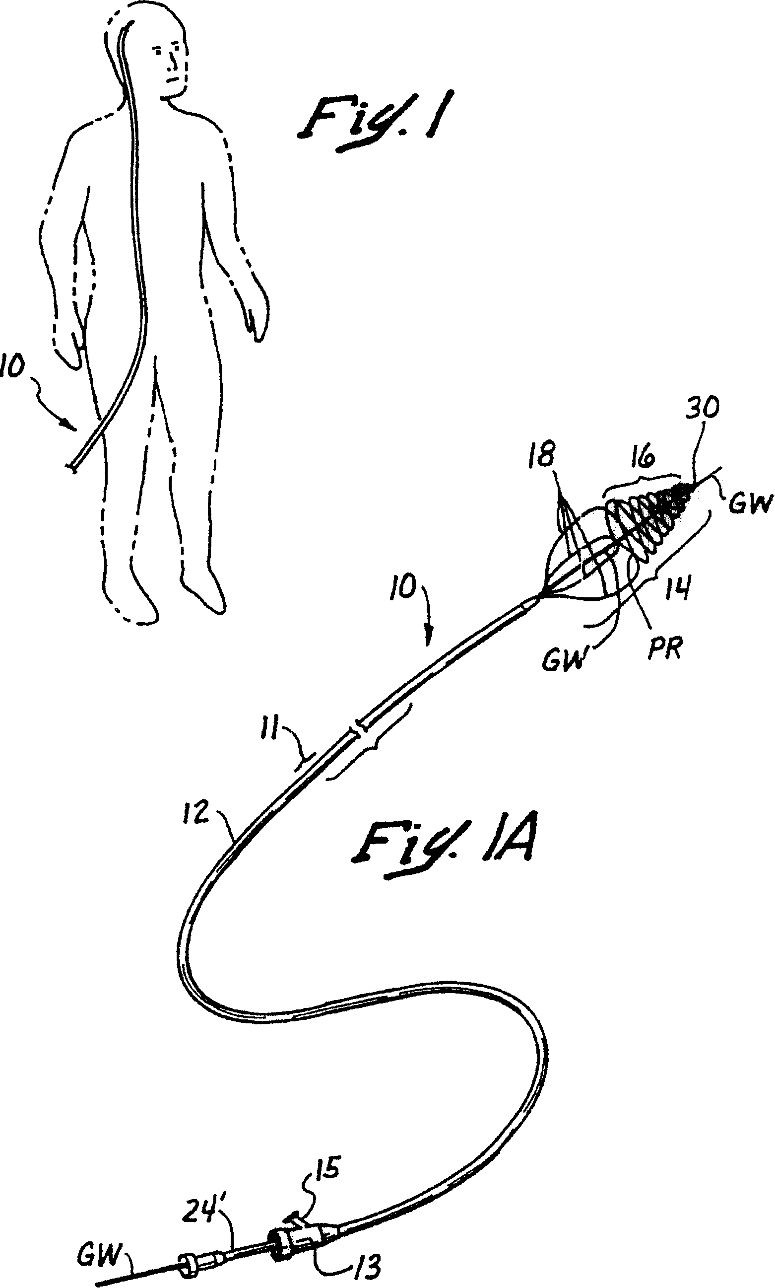
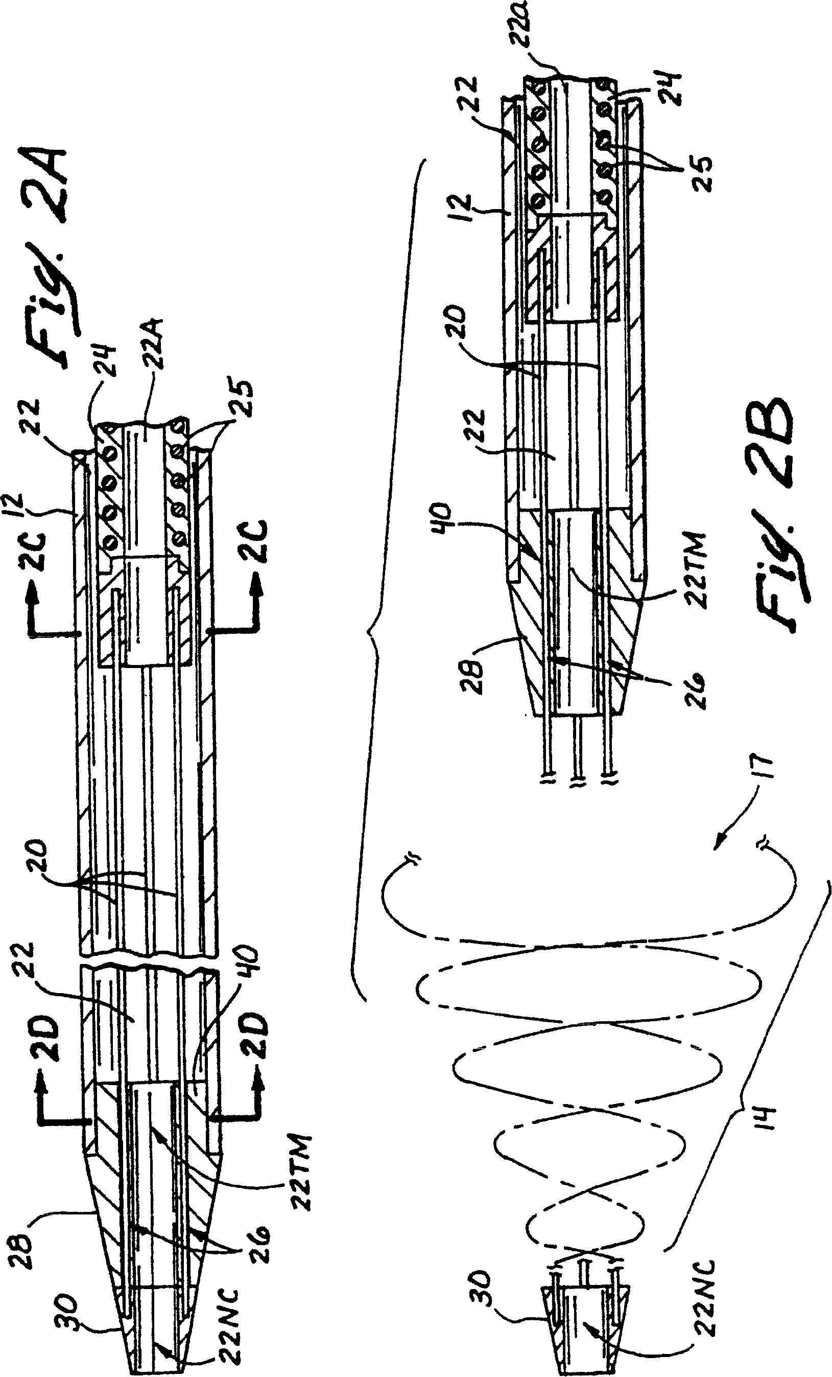
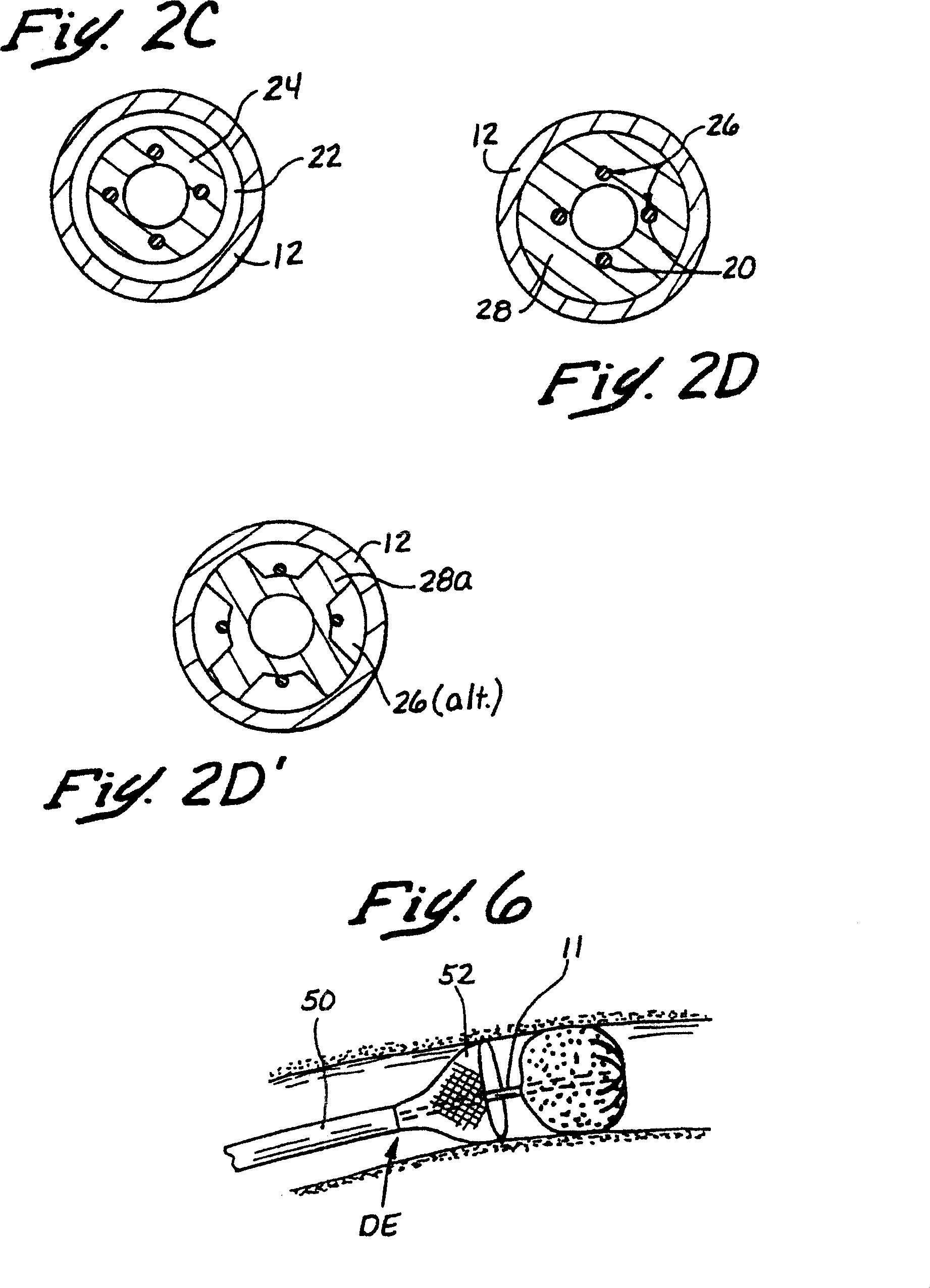
[0118] As shown in Figures 1-2D, a first embodiment of a full-line catheter device 10 includes an elongated, flexible catheter 11 having a clot capture container deployable from its distal end DE. 14, as shown in the figure. The occluding material capture container 14 is formed by a plurality (e.g., two or more) of wire elements 20 that are initially collapsible into a substantially rectilinear configuration within the catheter 11 and positioned at First (ie, loaded) position (see Figure 2A). When it is desired to deploy the obstructing substance capture container 14, the preformed wire element 20 is kept still while the catheter 11 is withdrawn, or the wire element 20 is advanced in the distal direction while the catheter 11 is not moved so that the wire Released from the constraints of the catheter 11 and elastically assumes a second (i.e., operable) configuration, in this configuration, the distal portion of the wire element forms an open proximal mouth or edge 17. The sp...

no. 2 approach

[0124] Figures 3B and 3B' illustrate a second embodiment of a full line catheter set 10' which differs from the first embodiment 10 in several ways. For example, the blocking material capture container (not shown) of this second embodiment is made of only two (2) wire elements 20' instead of four (4) wire elements as in the first embodiment 10. production. Moreover, the catheter 11' of the second embodiment incorporates a reduced diameter, increased flexibility elongated tip portion 270—the same tip portion as commercially available microcatheters (e.g., Prowler®). TM Microcatheter, Cordis Endovascular System, Miami Lakes, Florida) similar, an example of such a distal portion is shown in Figure 3A, which generally includes a proximal portion PP with a lumen L and a distal portion 270 with a lumen 271 , the lumen 271 communicates with the lumen L of the proximal portion PP.

[0125] Referring to Figures 3B and 3B', a second embodiment of the full-line embolectomy catheter dev...

no. 3 approach

[0130] 3D and 3D' show a third embodiment (i.e., a quick-change embodiment) of an embolectomy catheter device 10", which is similar in structure to the second embodiment 10' described above, but which introduces a guidewire access opening 267' formed in the sidewall of the catheter 11' adjacent the distal end of the proximal portion 12' thereof, and a guidewire deflector tube 260 extending from the guidewire access opening 267' to the lumen 22' '. Guidewire deflection tube 260' has an expanded distal end that is held in place centrally within the lumen by a plurality of radial support elements 264'. Longitudinal passageways 266, 266(alt) are formed in radial support elements 264' between, so that radiographic contrast agent or other fluids flow through lumen 22', over the expanded distal end of guidewire deflection tube 260'. Some longitudinal passages 266 (alt) are selected to be larger than others 266 so that an obstruction is formed The elongate element 20' of the substance...


PUM


Abstract

Embolectomy catheters, rapid exchange microcatheters, systems and methods for removing clots or other obstructive material (e.g., thrombus, thromboemboli, embolic fragments of atherosclerotic plaque, foreign objects, etc.) from blood vessels. This invention is particularly useable for percuatneous removal of thromboemboli or other obstructive matter from small blood vessels of the brain, during an evolving stroke or period of cerebral ischemia. In some embodiments, the embolectomy catheters of this invention are advanceable with or over a guidewire (GW) which has been pre-inserted through or around the clot. Also, in some embodiments, the embolectomy catheters include clot removal devices which are deployable from the catheter after the catheter has been advanced at least partially through the clot. The clot removal device may include a deployable wire nest that is designed to prevent a blood clot from passing therethrough. The delivery catheter may include telescoping inner and outer tubes, with the clot removal device being radially constrained by the outer tube. Retraction of the outer tube removes the constraint on the clot removal device and permits it to expand to its deployed configuration. An infusion guidewire is particularly useful in conjunction with the embolectomy catheter, and permits infusion of medicants or visualization fluids distal to the clot.

Description

technical field [0001] The present invention relates generally to medical methods and devices, and more particularly to embolectomy catheters and methods of using such catheters to remove blood clots or other material from the lumen of blood vessels or other anatomical catheters. Background technique [0002] Various types of thromboembolic diseases, such as stroke, emphysema, peripheral thrombosis, arteriosclerosis, etc., are known to occur in humans and other mammals. This thromboembolic disease is typically characterized by a thromboembolism (ie, a viscous blood clot including platelets, fibrinogen, and other clotting proteins) that deposits at a specific location in the blood vessel. [0003] When the thromboembolism is located in a vein, the obstruction caused by the thromboembolism produces symptoms of blood stasis, which develops in the vein so-called thrombophlebitis. Also, peripheral venous thrombosis may metastasize to other areas of the body, where even more seri...

Claims


Application Information

Patent Timeline
Patent Type & Authority Patents(China)
IPC IPC(8): A61M29/00A61B17/00A61B17/22A61M25/00
CPCA61B2017/22034A61B2017/22084A61M2025/109A61B17/320725A61B17/22A61M25/008A61B2017/00367A61B2017/22042A61B2017/22038A61B2017/22044A61M25/0068A61B2017/2212A61B17/32075A61B17/221A61B2017/00778
Inventor 罗伯特·F·罗森布鲁斯小乔治·R·格林布赖恩·J·考克斯托马斯·R·施特威勒肖恩·L·曹理查德·R·莫内蒂
Owner MICROVENTION INC
Why Eureka
Try Eureka