Photoelectric conversion optical fiber directly connected contact box structure for online monitoring high voltage temperature

A technology of photoelectric converters and contact boxes, applied in thermometers, thermometers using directly heat-sensitive electric/magnetic components, circuit breaker testing, etc., can solve major equipment and personal accidents, dangers, etc., to achieve anti-electromagnetic Strong interference ability, reliable and convenient online monitoring, and convenient equipment modification and replacement

Inactive Publication Date: 2007-09-12
陈津
View PDF1 Cites 5 Cited by
  • Summary
  • Abstract
  • Description
  • Claims
  • Application Information

AI Technical Summary

Problems solved by technology

However, when the optical fiber is exposed to the air and affected by pollution, conductive dust, moisture, etc., high voltage will be generated along the surface of the optical fiber to flashover, and the introduction of high voltage into the low-voltage control and communication system will cause major equipment and personal accidents, which is quite dangerous.

Method used


Image

  • Photoelectric conversion optical fiber directly connected contact box structure for online monitoring high voltage temperature
  • Photoelectric conversion optical fiber directly connected contact box structure for online monitoring high voltage temperature
  • Photoelectric conversion optical fiber directly connected contact box structure for online monitoring high voltage temperature

Examples


Embodiment 1

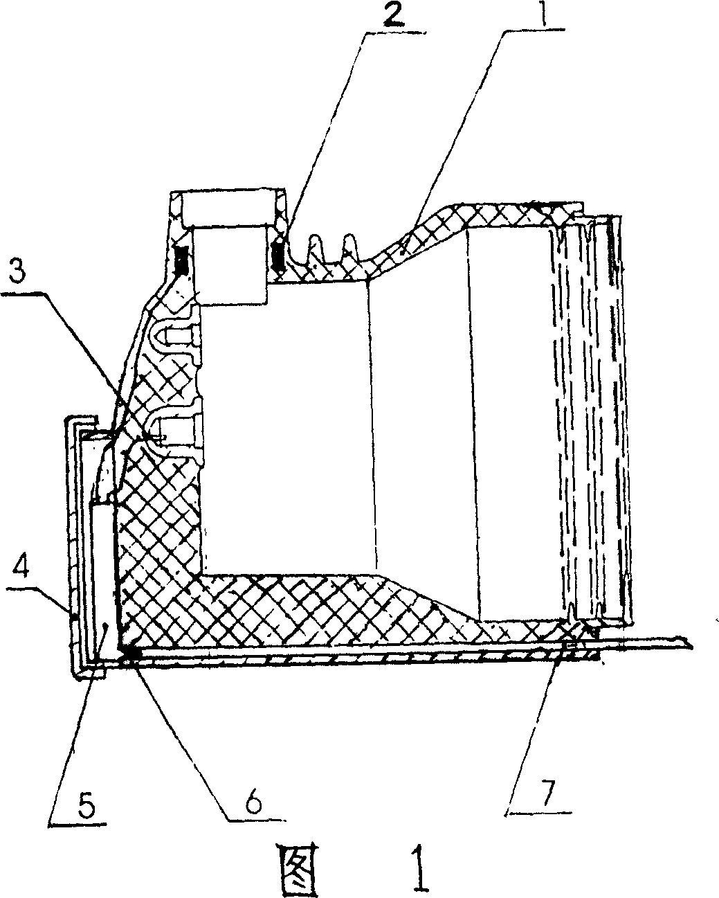
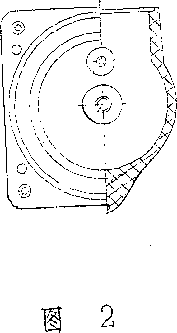
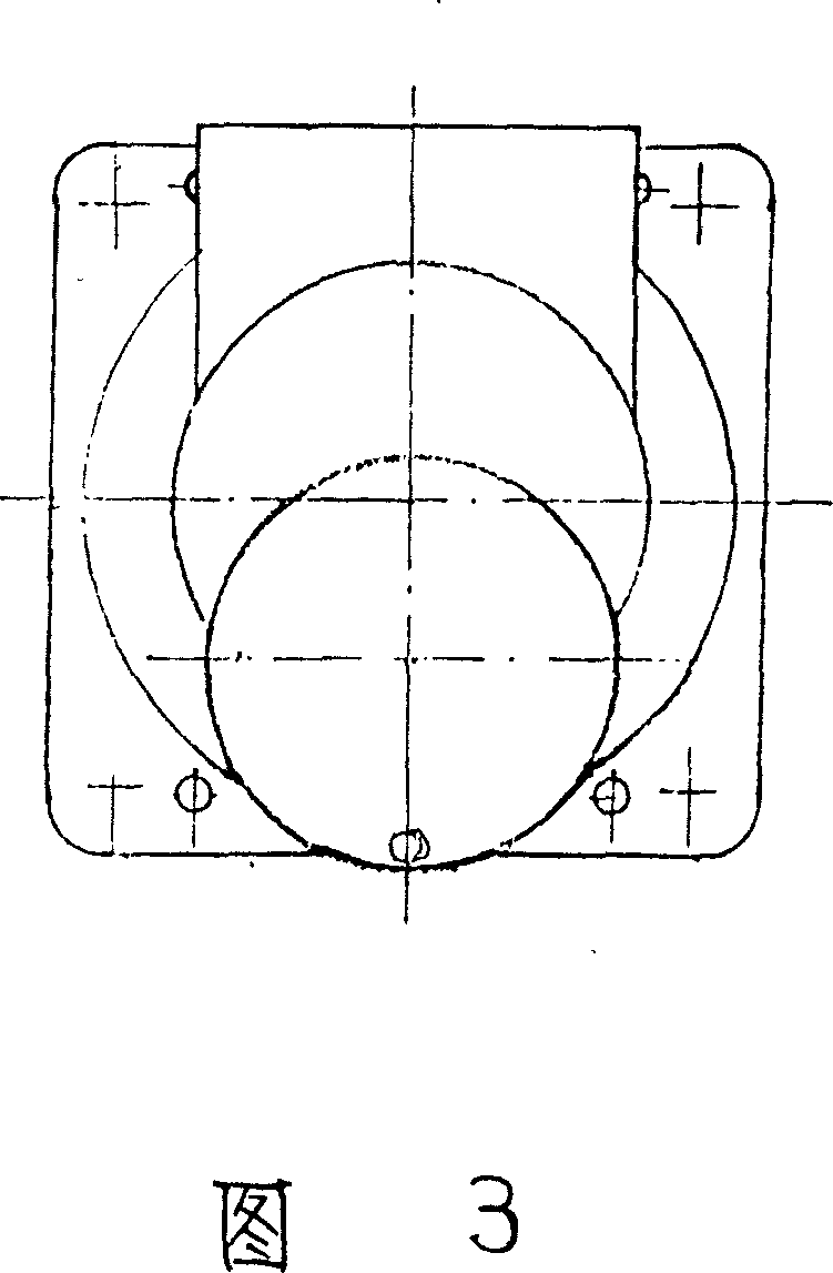
[0031] Please refer to Figure 1-Figure 3, there is a main body 1 of the contact box, a through hole is opened on the upper side of the main body 1, and the inductive power supply 2 in the insulator is injected into the inner side of the upper through hole of the main body 1, and the inductive power supply 2 passes through the lead wire Connect with the photoelectric converter 5 to provide its working power; the inner cavity of the main body 1 is embedded with a thermal detector 3 on the inner wall of the centerline position to fix the insert to detect the temperature of the static contact, and its lead wire is connected to the photoelectric converter 5 To input the temperature signal; the main body 1 is provided with a left and right transparent hole on the other side corresponding to the through hole at the upper end, and the left end of the hole is equipped with an infrared emission tube 6 connected to the photoelectric converter 5, and the infrared emission tube 6 is connecte...

Embodiment 2

[0033] Please refer to Figure 1-Figure 3 and Figure 8, there is a main body 1 of the contact box, and a through hole is opened on the upper side of the main body 1, and the inside of the upper through hole of the main body 1 is injected with the inductive power supply 2 in the insulator, the inductive power supply 2. Connect with the photoelectric converter 5 through the lead wire to provide its working power; the inner cavity of the main body 1 is fixed on the inner wall of the center line, and a thermal detector 3 is embedded in the insert to detect the temperature of the static contact. The lead wire and the photoelectric converter connected to the sensor 5 to input the temperature signal; the main body 1 is provided with a left and right transparent hole corresponding to the through hole at the side end, the left end of the hole is equipped with a side infrared emission tube 6 connected with the photoelectric transducer 5, and the infrared emission tube 6 Connect with the o...

Embodiment 3

[0035]Please refer to Figure 1-Figure 3 and Figure 9, there is a main body 1 of the contact box, and a through hole is opened on the upper side of the main body 1, and the inner side of the through hole on the upper side of the main body 1 is injected with the inductive power supply 2 in the insulator, the inductive power supply 2. Connect with the photoelectric converter 5 through the lead wire to provide its working power; the inner cavity of the main body 1 is fixed on the inner wall of the center line and embedded with a thermal detector 3 to detect the temperature of the static contact. The lead wire and the photoelectric converter connected to the sensor 5 to input the temperature signal; the main body 1 is equipped with an infrared emission tube 6 connected to the photoelectric converter 5 at the corresponding end of the upper through hole, the infrared emission tube 6 is connected to the directly embedded optical fiber 7, and the optical fiber 7 is connected to the exter...


PUM


Abstract

This invention relates to a kind of contact case structure of High Voltage temperature on-line monitoring that directly connect with photoelectric conversion optical fiber, belongs to high-voltage switch equipment's temperature on-line monitoring plant. The invention is a contact case structure, upper end of main body has blowhole; inlet influence power supply in interior of blowhole's inner, and power supply's feedthru connect with photoelectric transducer; embedding thermal detector on fixed unit of main body inner wall, and its feedthru connect with photoelectric transducer; top of main body set up cover at photoelectric transducer's location; opposite side of blowhole on the main body has set one penetrating slotted hole; and one side of slotted hole be furnished with ir emission tube that connect with photoelectric transducer; optical fiber penetrate slotted hole to connect with ir receiving tube on the control unit.

Description

technical field [0001] The invention relates to an on-line temperature monitoring device for a high-voltage switchgear, in particular to a contact box structure directly connected to a photoelectric conversion optical fiber for on-line high-voltage temperature monitoring. Background technique [0002] At present, due to the manufacturing and installation deviations of the moving and static contacts in the removable switchgear, as well as the mechanical vibration caused by electrical wear, mechanical operation and short-circuit electric power during the operation process, the contact resistance increases, causing the temperature to rise and aggravate the contact resistance. Oxidation of the contact surface leads to excessive local temperature and major equipment accidents occur frequently. This phenomenon has become the weak link of switchgear, so how to accurately and conveniently monitor its real temperature online is a subject of concern to people in the industry. [0003...

Claims


Application Information

Patent Timeline
Patent Type & Authority Applications(China)
IPC IPC(8): G01K7/22G01R31/327
Inventor 陈津
Owner 陈津
Why Eureka
Try Eureka