Method of providing a voIP connection

A downlink and terminal technology, applied to interconnection devices, electrical components, telephone communications, etc., to achieve efficient physical resource allocation, increase spectrum efficiency, and reduce signaling overhead

Active Publication Date: 2008-09-24
LUCENT TECH INC
View PDF0 Cites 14 Cited by
  • Summary
  • Abstract
  • Description
  • Claims
  • Application Information

AI Technical Summary

Problems solved by technology

However, this approach results in an even larger additional explicit signaling message

Method used


Image

  • Method of providing a voIP connection
  • Method of providing a voIP connection
  • Method of providing a voIP connection

Examples


Embodiment Construction

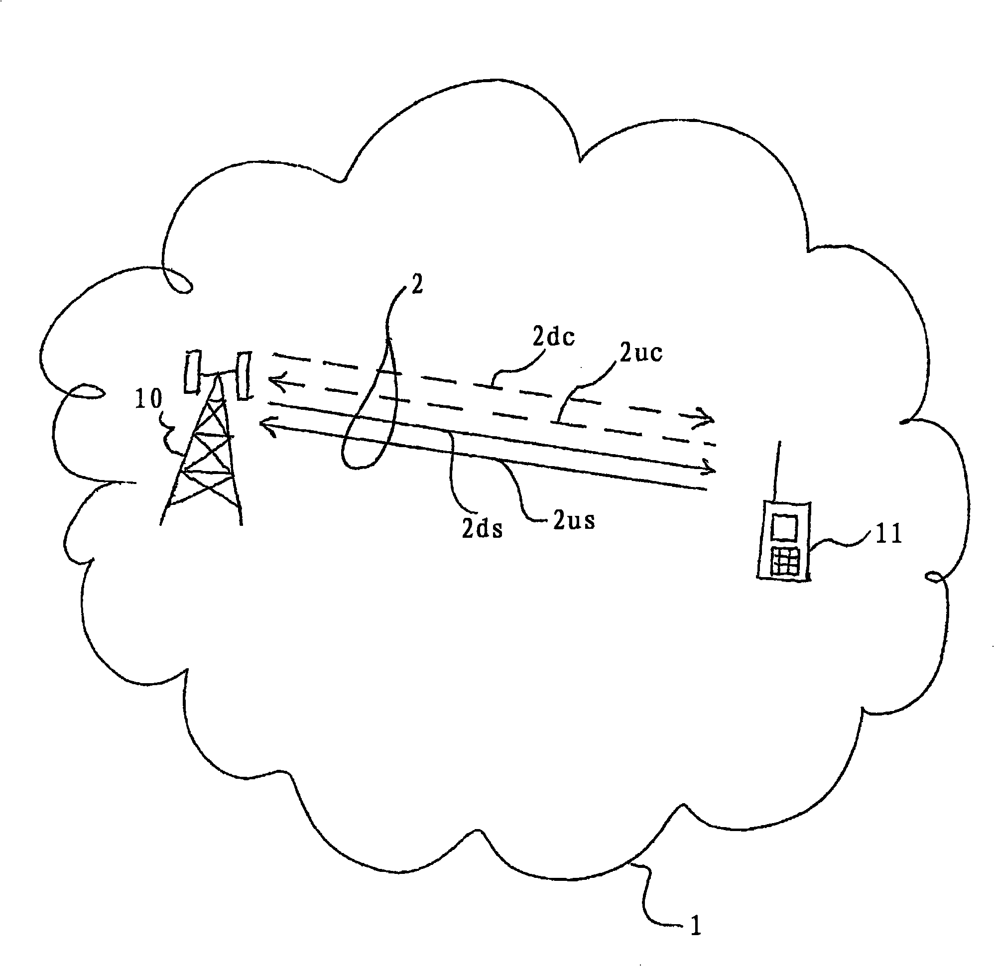
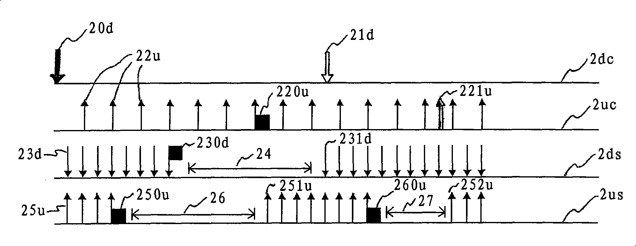
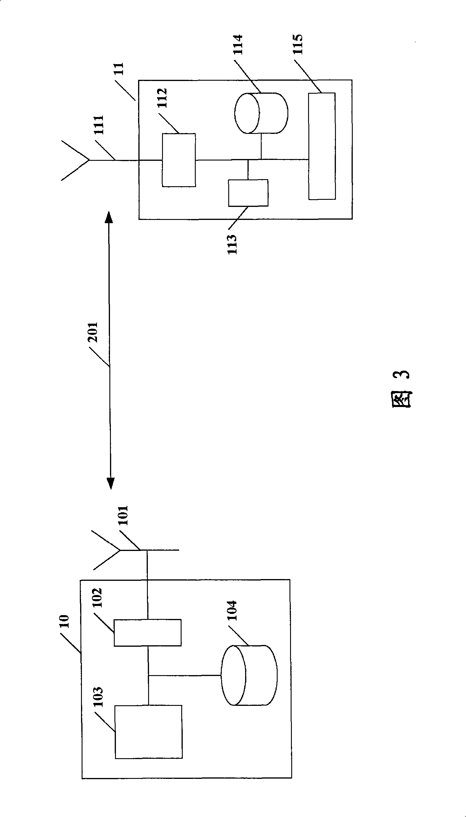
[0026] figure 1 Shown is a packet-based wireless communication system 1, a base station 10, a wireless mobile terminal 11, and a wireless communication link 2 between the base station 10 and the wireless mobile terminal 11, wherein the wireless communication link 2 includes a downlink control channel 2dc, uplink control channel 2uc, downlink data channel 2ds and uplink data channel 2us. The letter "s" in the notation 2ds and 2us indicates that the data sent on the data channel is "speech". Preferably, the wireless communication link 2 is a VoIP communication link.

[0027] The packet-based wireless communication system 1 may be any network system (eg a UMTS network) suitable for transmitting packet-based communication data. The base station 10 provides transmit and receive functionality for the wireless communication link 2 over the air interface. The base station 10 provides the wireless terminal 11 with connection to other wireless communication networks, or to a wired da...


PUM


Abstract

This invention concerns a method of providing a VoIP connection through wireless communication links of a packekbased wireless communication system, and a-corresponding base station and terminal. The wireless communication links comprise an uplink transmission path (2uc, 2us) from the terminal to the-base station, and a downlink transmission path (2dc, 2ds) from the base station to the terminal. Each of the uplink and downlink transmission paths (2uc, 2us, 2dc( 2ds) have a control channel (2uc, 2dc) and at least one data channel (2us, 2ds). Control messages (20d, 21d, 220u, 221u, 230d, 250u, 260u) are generated for scheduling network resources and for suspending and / or re-issuing a persistent grant of network resources allocated to the VoIP connection.

Description

technical field [0001] The invention relates to a method of providing VoIP connections via wireless communication links of a packet-based wireless communication system, and to base stations and terminals supporting such VoIP connections via wireless communication links (VoIP = Voice over Internet Protocol). Background technique [0002] In next-generation packet-based wireless systems like UMTS Long Term Evolution, VoIP will be the main service to be supported (UMTS = Universal System for Mobile Communications). However, VoIP data has unique business characteristics that differ from other packet data services. VoIP packets are very small, equal in size, are created periodically at fixed time intervals and face stringent delay and jitter requirements. [0003] Considering these characteristics, dynamic scheduling as for other data services would result in significant signaling overhead. With dynamic scheduling, the assigned transmission resources are explicitly signaled to ...

Claims


Application Information

Patent Timeline
Patent Type & Authority Applications(China)
IPC IPC(8): H04Q7/22H04Q7/38H04Q7/30H04M7/00H04W72/12H04W74/02
CPCH04W72/1289H04W72/04H04W72/1263H04W72/23H04W72/12
Inventor M·施奈德A·法尼沃洛R·巴赫尔
Owner LUCENT TECH INC
Why Eureka
Try Eureka