Method and system for basement engineering water proof and water drain

A drainage system and basement technology, applied in water conservancy projects, infrastructure projects, artificial islands, etc., can solve the problems of large drainage, difficult implementation, impossibility, etc., and achieve the effect of prolonging durability and reliability and improving waterproof effect

Inactive Publication Date: 2008-11-05
朱邃科 +2
View PDF2 Cites 52 Cited by
  • Summary
  • Abstract
  • Description
  • Claims
  • Application Information

AI Technical Summary

Problems solved by technology

Neither of the above two patent applications proposed the requirement of cutting off the groundwater, and the proposed scheme could not effectively prevent the groundwater from entering under the bottom plate, and the displacement was so large that it was impossible or difficult to calculate the power of the drainage pump, so it was difficult to implement; when the bottom plate When the bottom is a rock-soil layer with high water permeability, the amount of groundwater from under the floor is already very large; when the floor is a rock-soil layer with low water permeability, but the rock-soil above the floor has a large water permeability, the 200610062166.1 patent application For the 200510038548.6 patent application, a large amount of groundwater can easily bypass the bottom surface of the outer wall and reach under the indoor floor, because the plain concrete in the material used to block groundwater is easy to crack and permeable, and the bottom surface of the concrete If the contact surface with the bottom of the foundation pit is not properly treated, it will become a permeable channel for groundwater and rainwater from the ground. The rock and soil surface at the bottom of the foundation pit and slope cannot be in close contact with asphalt, so it is impossible to effectively block groundwater Access under the floor of the basement

Method used


Image

  • Method and system for basement engineering water proof and water drain
  • Method and system for basement engineering water proof and water drain
  • Method and system for basement engineering water proof and water drain

Examples


Embodiment

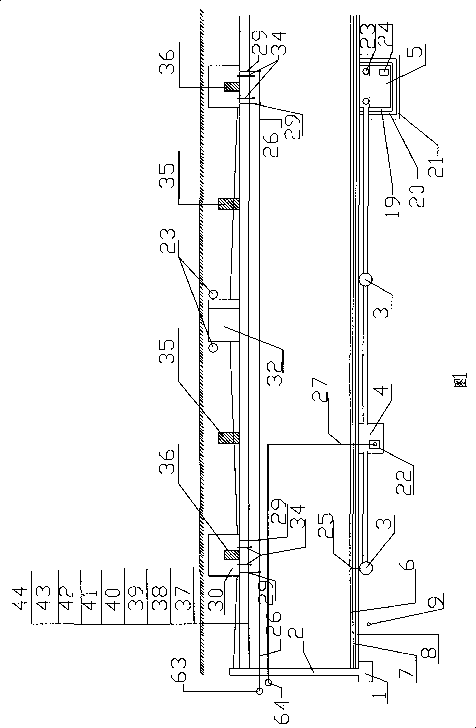
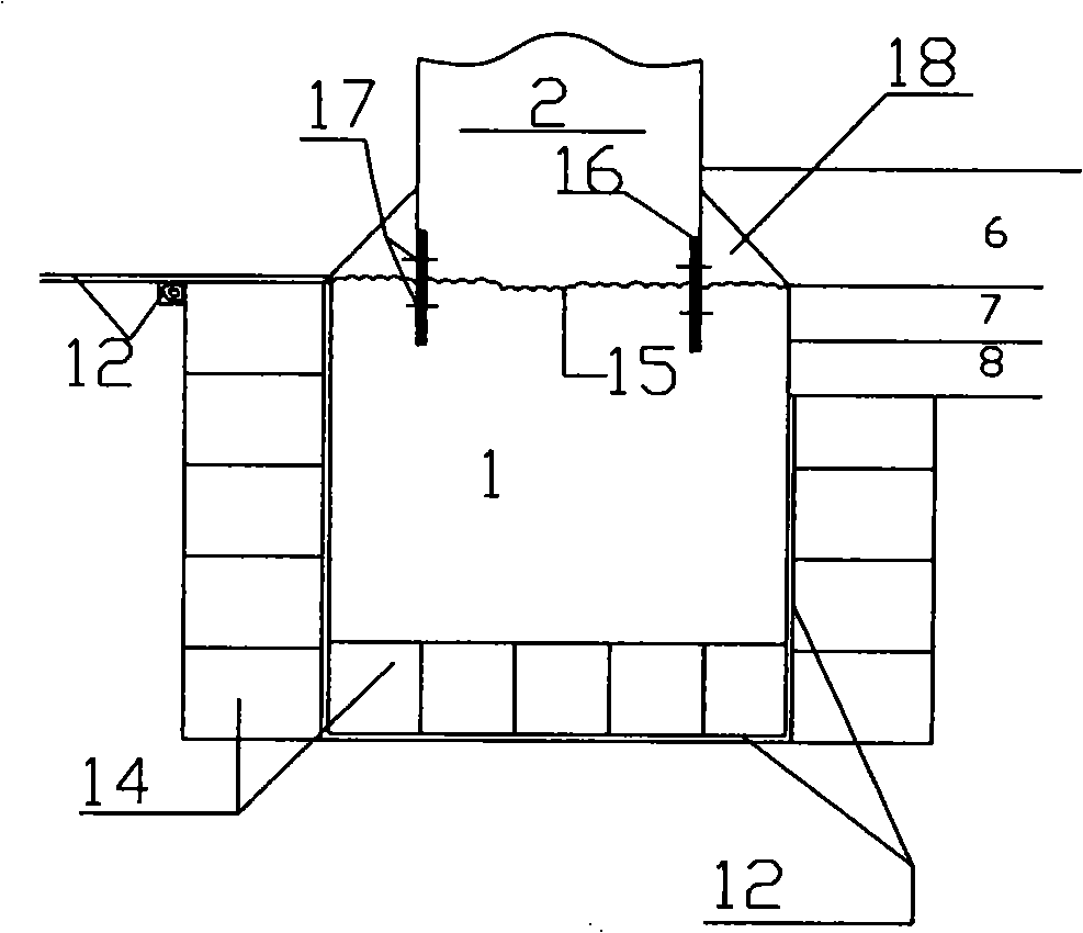
[0048] As shown in Figure 1, the wall base (1) of the basement engineering outer wall (2) goes deep into a certain depth in the foundation (9) of the impermeable or slightly water-permeable rock soil layer or soft soil layer, when the foundation (9) is soft For the soil layer, the soft soil foundation should be treated in advance to form a continuous thick layer of cement-soil layer, that is, all the soil layers within a certain depth range below the basement surface elevation within the range of 2-5m outside the basement project should be used. Cement reinforcement treatment forms a continuous impermeable cement-soil water-resisting layer in the horizontal direction and serves as the bearing base of the floor. The thickness of the cement-soil is at least greater than 1.5m.

[0049] The wall base (1) is supplemented with detailed water interception measures to prevent the groundwater outside the outer wall (2) from entering under the bottom plate (6) through the bottom surface ...


PUM


Abstract

A basement engineering waterproof and drainage method is provided. The wall footing of the outside wall in basement engineering is embedded in watertight or micro-watertight soil rock layer or cement soil layer. The wall footing intercepts water by a thin-part structure. The cushion of the basement engineering soleplate and the falling layer of the top board are composed of combined water-proof layers. The late poured band, the movement joint and the horizontal construction joint at the lower part of the outside wall are treated by a water-proof structure combined with waterproofing measures. The basement engineering is provided with a drainage system. The groundwater and surface water at the soleplate are drained into city drainage pipelines via a soleplate part of the drainage system. The rainwater of overburden layer bottom of the top board is then drained into city drainage pipelines via the indoor part of the drainage system. The invention is designed by adopting a one-body method of arranging the basement engineering waterproofing, drainage and anti-floating as well as underground engineering space enclosing structure and pipelines, thereby shortening the construction period, reducing the engineering cost, increasing the durability and reliability of underground building space enclosing structure and waterproof layer as well as pipelines.

Description

technical field [0001] The invention relates to the construction field, in particular to a basement engineering waterproof and drainage method and system. Background technique [0002] The traditional basement engineering design is to place the bottom plate and outer wall of the basement enclosure structure in groundwater, and the rainwater at the bottom of the roof layer is drained to the outside on the top surface of the roof, and a special waterproof layer is used to isolate the water from the enclosure structure to protect the building. Structural parts are used to resist the buoyancy and infiltration of water. The anti-floating design water level is higher than the highest water level in the year. This design method leads to complex enclosure structures, waterproofing and drainage methods. When the basement is large, the drainage path on the top of the roof is very long , The bottom plate and exterior wall structural components and the roof slope are too thick, the cons...

Claims


Application Information

Patent Timeline
Patent Type & Authority Applications(China)
IPC IPC(8): E02D31/02E02D19/20E02D29/045
Inventor 朱邃科朱文江夏勇
Owner 朱邃科
Why Eureka
Try Eureka