Power battery pack device convenient for changing installation position

A technology for battery pack devices and power battery packs, which is applied in the directions of power devices, electric power devices, transportation and packaging, etc., which can solve problems such as inconvenient feeling, inconvenient disassembly and assembly of battery packs, and occupying space on the vehicle frame, so as to improve stability sexual effect

A technology for battery pack devices and power battery packs, which is applied in the directions of power devices, electric power devices, transportation and packaging, etc., which can solve problems such as inconvenient feeling, inconvenient disassembly and assembly of battery packs, and occupying space on the vehicle frame, so as to improve stability sexual effect

CN101306642AInactive Publication Date: 2008-11-19GUANGZHOU ZHANHUI ELECTRONICS

Image

  • Power battery pack device convenient for changing installation position
  • Power battery pack device convenient for changing installation position
  • Power battery pack device convenient for changing installation position

Examples


Embodiment Construction

[0029] Below in conjunction with the best embodiment shown in the accompanying drawings, it will be further described in detail.

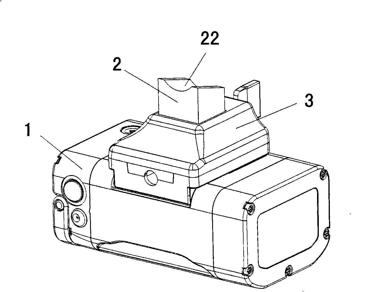
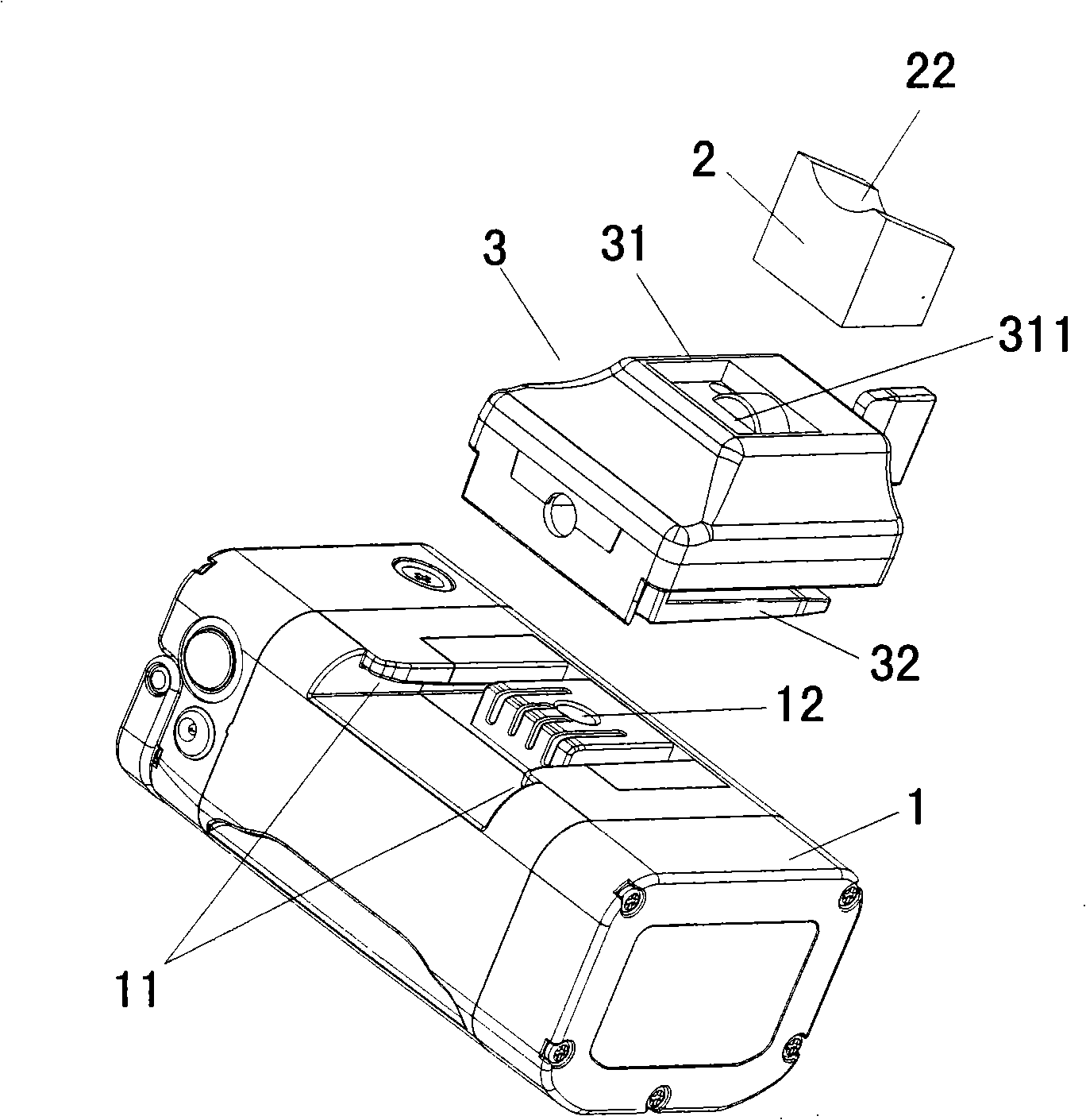
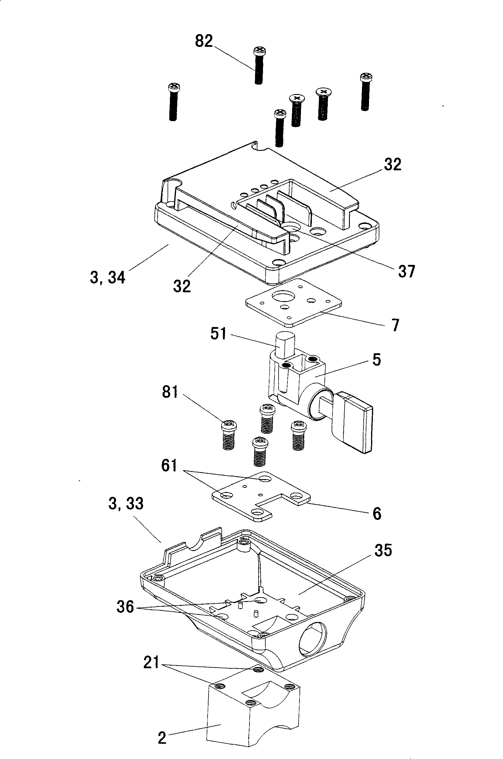
[0030] Such as figure 1 and figure 2 As shown, the power battery pack device for conveniently changing the installation orientation of the present invention is mainly composed of the main body 1 of the battery pack device and the suspension assembly arranged on the back of the main body 1 of the battery pack device. Seat 2, connecting seat 3 for connecting battery pack device main body 1 and fixing seat 2, and locking device 5 installed on the connecting seat 3 for locking the battery pack device main body 1 on the suspension assembly.

[0031] Such as image 3 As shown, there are four screw holes 21 on the side where the fixed base 2 is connected with the coupling base 3, such as figure 2 As shown in Fig. 4, the connection surface 22 between the fixed seat 2 and the vehicle frame is an inner concave surface matching the curvature of the conne...


PUM


Abstract

The invention provides a power battery pack device with facilitation of changing installation direction and position. The power battery pack device comprises a main body (1) and a suspension assembly arranged on the back surface of the main body (1). The suspension assembly comprises a fixed seat (2) fixedly connected with a vehicle frame, a coupled seat (3) and a locking device (5) mounted on the coupled seat (3). The coupled seat (3) is provided with a fixed seat engagement part (31) which is detachably connected with the fixed seat and a main body slicing part (32) which is connected with the main body (1). The installation direction and position of the main body (1) can be changed by determining the fixing position of the fixed seat (2) on the vehicle frame. The locking device (5) is used to lock the main body (1) on the suspension assembly. The installation direction and position of the power battery pack device are easy to change according to the requirement. The power battery pack device is widely used in powder devices such as electric bicycles.

Description

technical field [0001] The invention relates to a power supply device, in particular to an installation structure of a battery pack device for powering an electric bicycle. Background technique [0002] Most of the power battery packs of existing electric bicycles are installed on the front beam of the bicycle or the rear standpipe of the vehicle frame. For example, some are obliquely fixed on the rear standpipe of the vehicle frame. After the power battery is assembled, the battery pack and the box-type device are fixedly connected together with screws from the bottom of the box-type device; Finally, fix the battery pack with screws from the bottom of the frame. The above installation structure of the battery pack limits the installation position of the battery pack, so that it can only be installed on a fixed position of the vehicle frame such as the rear riser, and the installation of the battery pack at this position not only takes up the limited space between the vehic...

Claims


Application Information

Patent Timeline
19 Nov 2008
Publication
CN101306642A
IPC
B60K1/04; B62J39/00; B62J99/00; H01M50/258
CPC
Y02E60/10
Inventors
李智; 董超祺