Bidirectional cooling LED apparatus

A technology of light-emitting diodes and two-way heat dissipation, which is applied to lighting devices, components of lighting devices, semiconductor devices of light-emitting elements, etc., can solve problems such as damage to light-emitting diode chips, single heat conduction path, and inability to dissipate heat in a timely manner. Avoid damage and increase the effect of heat dissipation path

Inactive Publication Date: 2011-07-27
EVERLIGHT ELECTRONICS
View PDF0 Cites 0 Cited by
  • Summary
  • Abstract
  • Description
  • Claims
  • Application Information

AI Technical Summary

Problems solved by technology

As the power of LED chips increases, heat is generated faster and faster. This single heat conduction path cannot dissipate heat in time, which will cause damage to LED chips.

Method used


Image

  • Bidirectional cooling LED apparatus
  • Bidirectional cooling LED apparatus
  • Bidirectional cooling LED apparatus

Examples


Embodiment Construction

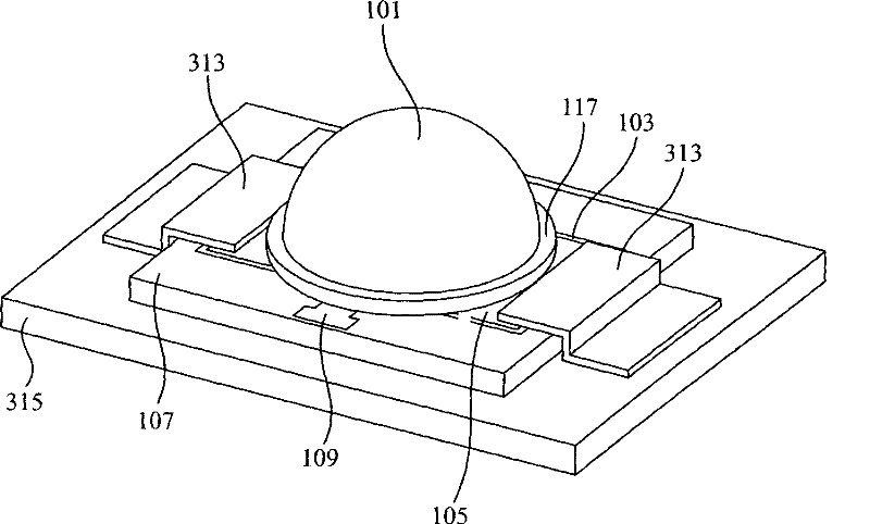
[0024] In the bidirectional heat dissipation LED device of the following embodiments, the heat generated by the LED chip can be dissipated to the heat dissipation substrate and the outside through the main body portion and the extension portion of the heat dissipation material respectively. Furthermore, heat dissipation fasteners can be added to fasten the extension of the heat dissipation material and the heat dissipation substrate, so that the light emitting diodes, the heat dissipation material, and the heat dissipation substrate are tightly bonded to increase heat dissipation efficiency.

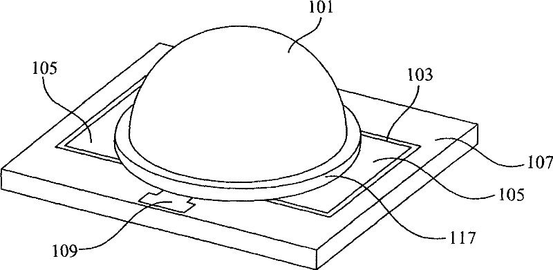
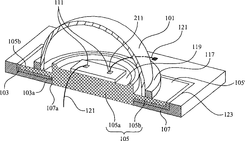
[0025] Please also refer to figure 1 as well as figure 2 , which are respectively a perspective view and a cross-sectional view of a bidirectional heat dissipation LED device according to an embodiment of the present invention. The bidirectional heat dissipation LED device includes a heat dissipation material 105 and an LED chip 211 disposed on the heat dissipation material 105 . The ...


PUM


Abstract

The invention discloses a bilateral heat elimination light emitting diode device, which comprises a light emitting diode chip, heat elimination material, a plastic cladding piece and a circuit base plate. The heat elimination material comprises a main body part for bearing the light emitting diode chip, and an extending part coupled with the main body part. The heat of the light emitting diode chip is respectively emitted through the main body part and the extending part. The plastic cladding piece bears and exposes the extending part to the air, to ensure the heat of the light emitting diodechip is emitted to the air through the extending part. The circuit base plate contains the plastic cladding piece through a notch, and the main body part penetrates the first hollow area of the circuit base plate and the second hollow area of the plastic cladding piece. The bilateral heat elimination light emitting diode device ensures the heat elimination paths of the heat elimination material to be increased, and ensures the heat generated through the light emitting diode chip to be effectively emitted through the heat elimination material, thereby the damage to the light emitting diode chip is avoided.

Description

technical field [0001] The invention relates to a light emitting diode device, in particular to a packaging structure of the light emitting diode device. Background technique [0002] With the advancement of technology, light emitting diodes (Light Emitting Diode; LED) have low working voltage, low power consumption, high luminous efficiency, short reaction time, pure light color, firm structure, shock resistance, vibration resistance, stable and reliable performance, Due to the characteristics of light weight, small size and low cost, its application fields are becoming more and more extensive, such as: large-area graphic display full-color screen, status indication, sign lighting, signal display, backlight of liquid crystal display or interior lighting. [0003] In a conventional LED device, one surface of the heat dissipation material bears the LED chip, and the other surface penetrates the circuit substrate to contact the heat dissipation substrate. The heat generated b...

Claims


Application Information

Patent Timeline
Patent Type & Authority Patents(China)
IPC IPC(8): F21V29/00H01L23/367H01L23/373F21V5/04F21Y101/02F21V29/503F21V29/70F21V29/85F21Y115/10
CPCH01L2924/0002
Inventor 裴建昌
Owner EVERLIGHT ELECTRONICS
Why Eureka
Try Eureka