Boiler heat supplying climate compensating system and its implementing method

A climate compensation and boiler technology, which is applied in heating systems, hot water central heating systems, heating methods, etc., can solve the problems of boiler acid corrosion, high investment costs, and small boiler flow, so as to avoid the danger of pipe burst and facilitate transformation , the effect of saving energy

Active Publication Date: 2011-06-15
BEIJING SHUOREN TIMES TECH
View PDF0 Cites 0 Cited by
  • Summary
  • Abstract
  • Description
  • Claims
  • Application Information

AI Technical Summary

Problems solved by technology

However, the system has the following defects in the following three aspects: First, the inlet water temperature of the boiler is equal to the return water temperature of the heating system. The dew point temperature of the medium water vapor will eventually lead to acid corrosion on the heating surface of the boiler tail; secondly, part of the return water flow of the heating system directly enters the water supply pipe through the bypass pipe, and the flow into the boiler may be relatively small, which will be lower than that of the boiler. The minimum value of the rated flow rate may cause the boiler convection tube bundle to burst due to poor water flow; again, because the flow rate entering the boiler may be too small, the power saving effect is not obvious after the system circulating water pump adopts a frequency conversion device
The system makes up for figure 1 The above defects of the system shown, but there are still the following two defects: first, the main circulating water pump of the heating system runs at high temperature, which will affect the service life of the circulating water pump; second, the heating system that has been built and is currently in operation , generally a single-stage pump system, that is, the main circulation pump of the system is in the inlet area of ​​the boiler, if it is to be changed into figure 2 If the climate compensation system shown is not used, the main circulating water pump must be replaced, so that the transformation investment cost is relatively large

Method used


Image

  • Boiler heat supplying climate compensating system and its implementing method
  • Boiler heat supplying climate compensating system and its implementing method
  • Boiler heat supplying climate compensating system and its implementing method

Examples


Embodiment Construction

[0048] The following examples are used to illustrate the present invention, but are not intended to limit the scope of the present invention.

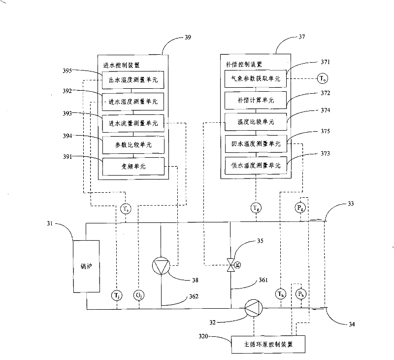
[0049] image 3 It is a schematic diagram of Embodiment 1 of the boiler heating climate compensation system of the present invention. As shown in the figure, the system includes a boiler 31, a main circulation water pump 32 for system water supply and system return water circulation, a water supply pipe 33 connected to the boiler water outlet, And the return pipe 34 that is connected with boiler water inlet, also includes:

[0050] The electric regulating valve 35 is arranged on the first bypass pipe 361 connecting the water supply pipe 33 and the return pipe 34, and is used to adjust the mixing ratio of the system return water flowing into the boiler outlet water; the compensation control device 37 is calculated according to the obtained outdoor meteorological parameters The heating temperature reference value is compared with the he...


PUM


Abstract

The invention relates to a boiler heat supply climate compensation system, which comprises a boiler, a main circulating water pump for water supply and return water circulation of the system, a water supply pipe which is connected with a water outlet of the boiler and a water return pipe which is connected with a water inlet of the boiler, and the boiler heat supply climate compensation system further comprises: an electric regulating valve for regulating the mixing proportion of discharge water of the return water of the system which flows into the boiler; a compensation control device for regulating the opening degree of the electric regulating valve according to the obtained outdoor meteorological parameters and leading the heat supply temperature measurement value to achieve the givenheat supply temperature reference value; an auxiliary circulating water pump for pressurizing the outlet water of the boiler to be mixed with the return water of the system to enter the boiler; and awater inlet control device for controlling the working frequency of the auxiliary circulating water pump and leading the water inlet temperature and the flow rate of the boiler to achieve the minimumdemand value. The invention further relates to a realization method of the boiler heat supply climate compensation. The technical proposal of the invention can ensure the requirements on the water inlet temperature and the minimum flow rate of the boiler at the same time of realizing the climate compensation, thereby achieving the purpose of saving energy and avoiding the potential danger of pipeexplosion.

Description

technical field [0001] The invention relates to heat supply technology, in particular to a boiler heating climate compensation system and its realization method. Background technique [0002] At present, most of the boiler rooms for heating are operated and managed manually. The gas or coal is more or less based on the feeling of the fireman. The extensive management usually leads to unstable indoor temperature and waste of heat energy. Considering the reliability and comfort of the operation of the above-mentioned boiler heating system, products such as climate compensators have appeared in the prior art. According to the difference in climate and outdoor temperature, as well as the temperature fluctuation and light change of the day, through adjustment The water supply temperature of the system, so that the heat supply of the system matches the outdoor environment climate and weather, achieves the purpose of heating on demand, and also ensures the minimum inlet water tempe...

Claims


Application Information

Patent Timeline
Patent Type & Authority Patents(China)
IPC IPC(8): F24D3/02F24D3/10F24D19/10F24H9/12
CPCY02B30/745Y02B30/70
Inventor 史登峰
Owner BEIJING SHUOREN TIMES TECH
Why Eureka
Try Eureka