Adjustment mechanism of gear-face profiling chamfering device

A technology of adjusting mechanism and gear end, which is applied in the direction of gear cutting machine, mechanical equipment, and components with teeth, etc. It can solve the problems such as difficult control of chamfer size, complicated transmission and indexing mechanism, and inability to realize full tooth chamfering. Achieve the effects of precise control of chamfering size, simple structure and high chamfering efficiency

Inactive Publication Date: 2009-05-06
江苏南方机电股份有限公司
View PDF0 Cites 6 Cited by
  • Summary
  • Abstract
  • Description
  • Claims
  • Application Information

AI Technical Summary

Problems solved by technology

Most of these chamfering methods have the following defects: the size of the chamfering is not easy to control, the chamfering in the direction of the tooth height is uneven, the full tooth chamfering cannot be realized, and the chamfering effect near the bottom of the tooth is poor; The limitation of the application range is narrow; the transmission and indexing mechanism are more complicated and the cost is high; the chamfering efficiency is low

Method used


Image

  • Adjustment mechanism of gear-face profiling chamfering device
  • Adjustment mechanism of gear-face profiling chamfering device
  • Adjustment mechanism of gear-face profiling chamfering device

Examples


Embodiment Construction

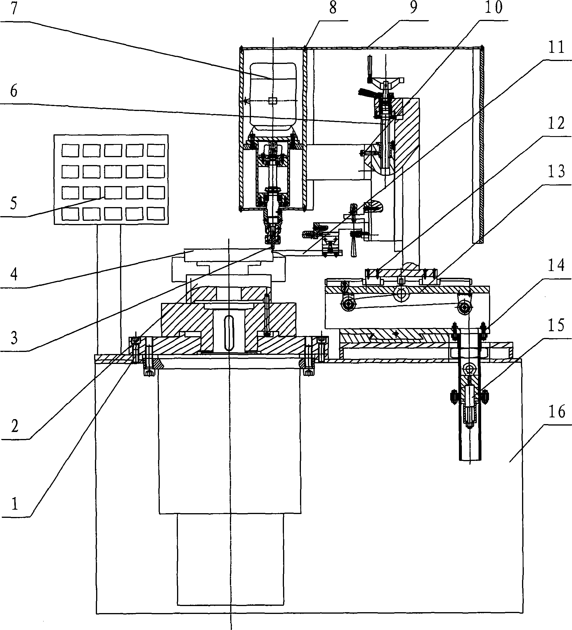
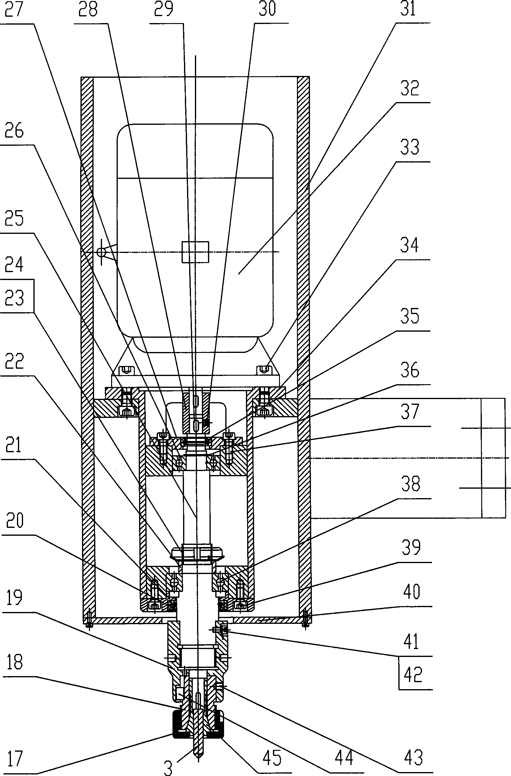
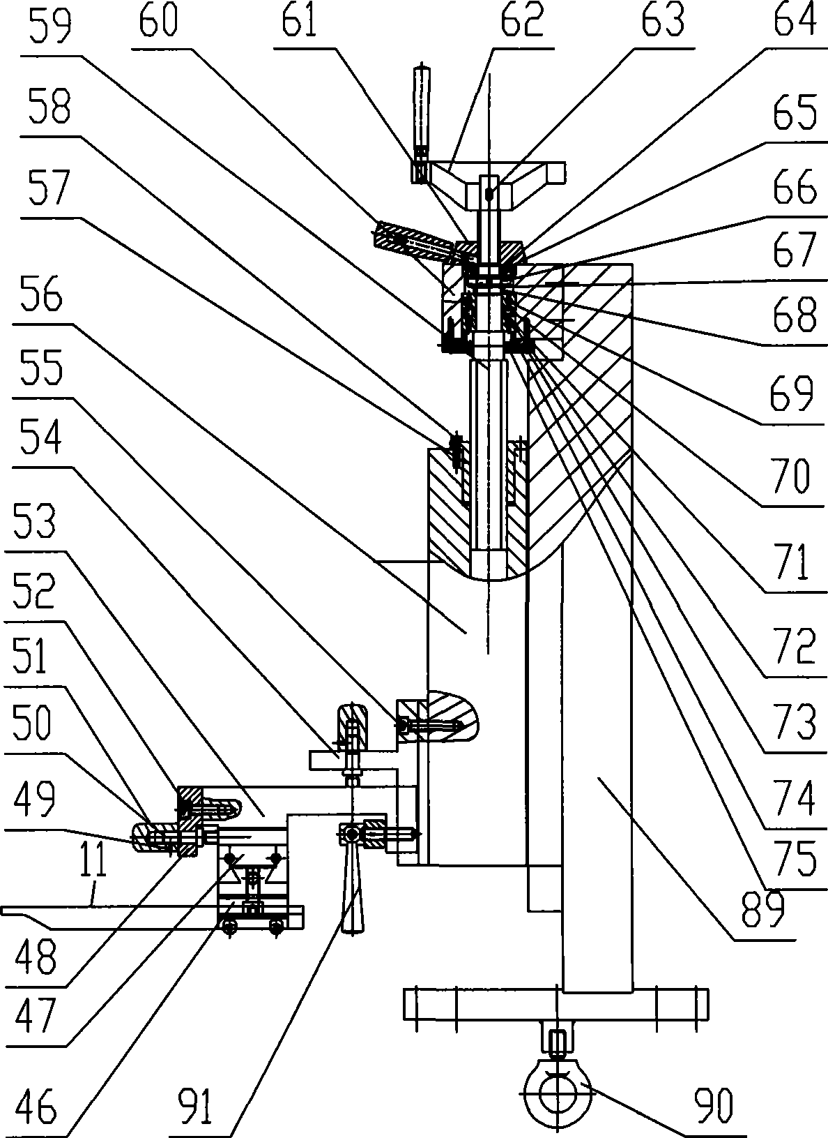
[0019] 1. Screw, 2. Fixture device, 3. Tool, 4. Workpiece (gear), 5. Control panel, 6. Adjusting mechanism, 7. Power head device, 8. Screw, 9. Cover, 10. Screw, 11 , Profiled contact, 12, screw, 13, linear guide pair, 14, screw, 15, constant force device, 16, bed, 17, lock nut, 18, transition sleeve, 19, coupling sleeve, 20, seal Ring, 21, lower bearing cover, 22, spacer, 23, stop washer, 24, round nut, 25, shaft, 26, bearing, 27, upper bearing cover, 28, sleeve coupling, 29 , flat key, 30, set pin, 31, support, 32, motor, 33, screw, 34, sleeve, 35, sealing ring, 36, circlip for shaft, 37, screw, 38, bearing, 39, Screw, 40, lower cover of protective cover, 41, screw, 42, washer, 43, set screw, 44, flat key, 45, collet, 46, Y-direction sliding seat, 47, X-direction sliding seat, 48 , middle fixing plate, 49, pin, 50, first screw rod, 51, first scale knurled nut, 52, screw, 53, Z-direction sliding seat, 54, upper fixing plate, 55, screw, 56, first Slider, 57, nut, 58, screw, 5...


PUM


Abstract

The invention relates to a regulating mechanism for a copying chamfering device on the end surface of a gear. According to the technical proposal provided by the invention, in the regulating mechanism, a copying contact is arranged on a Y-direction sliding seat which is connected with an X-direction sliding seat; a stop block is fixed on a lower fixed plate; a fourth screw rod is screwed in the threaded hole of the Y-direction sliding seat; the lower fixed plate is sheathed on the fourth screw rod and is fixed on the X-direction sliding seat; the X-direction sliding seat is connected with a Z-direction sliding seat; a first screw rod is screwed in the threaded hole of the X-direction sliding seat; a middle fixed plate is sheathed on the cylindrical surface of the first screw rod and is fixed on the Z-direction sliding seat; the Z-direction sliding seat is arranged on an upper fixed plate which is sheathed on a third screw rod; the third screw rod is screwed in the threaded hole of the Z-direction sliding seat; the upper fixed plate is fixed on a first slider; a nut is fixed in the inner hole of the first slider; and the first slider is arranged on a regulating frame which is fixed on a slider in a linear guide pair. The regulating mechanism can realize accurate control on the chamfering size, and the chamfering is carried out in full tooth uniformly along the tooth depth direction, thus improving the chamfering quality.

Description

technical field [0001] The invention relates to an adjustment mechanism of gear end face profiling and chamfering equipment, which belongs to the technical field of mechanical manufacturing. Background technique [0002] With the rapid development of the economy, industries such as general machinery, automobiles, motorcycles, and coal mining are also increasingly prosperous. The production of gears that transmit power and motion while changing speed and steering required by these industries has also entered the era of mass production. Gear manufacturers are faced with such a problem during mass production: during the gear machining process, sharp edges and burrs remain on the gear end face. And these sharp edges and burrs directly affect the quality of the gear: if these sharp edges and burrs are not removed, they will become very hard after carburizing and quenching, and the tooth edges will easily chip when the subsequent gear is finished. It will scratch the tooth surfa...

Claims


Application Information

Patent Timeline
Patent Type & Authority Applications(China)
IPC IPC(8): B23F19/10B23F23/00
Inventor 杨诗斌张升学盛永嘉苏靖
Owner 江苏南方机电股份有限公司
Why Eureka
Try Eureka