Gear chamfering device

A chamfering and gear technology, applied in the direction of belts/chains/gears, gear teeth, components with teeth, etc., can solve the problems of poor uniformity and low chamfering precision, and achieve high centrality, high qualified rate of finished products, Effect of improving chamfering efficiency

Active Publication Date: 2022-05-13
CHONGQING JUJIA MACHINERY
View PDF6 Cites 0 Cited by
  • Summary
  • Abstract
  • Description
  • Claims
  • Application Information

AI Technical Summary

Problems solved by technology

Some existing large-scale gear chamfering equipment, when chamfering the gear edge, align the chamfering knife with the gear, and then move the gear toward the direction of the gear knife through the transmission mechanism to realize the chamfering. Most of the cutting tools are judged by manual proficiency, resulting in low precision and poor uniformity of chamfering

Method used


Image

  • Gear chamfering device
  • Gear chamfering device
  • Gear chamfering device

Examples


Embodiment 1

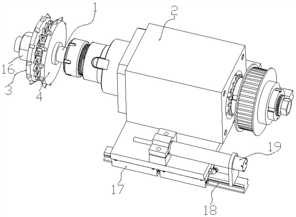
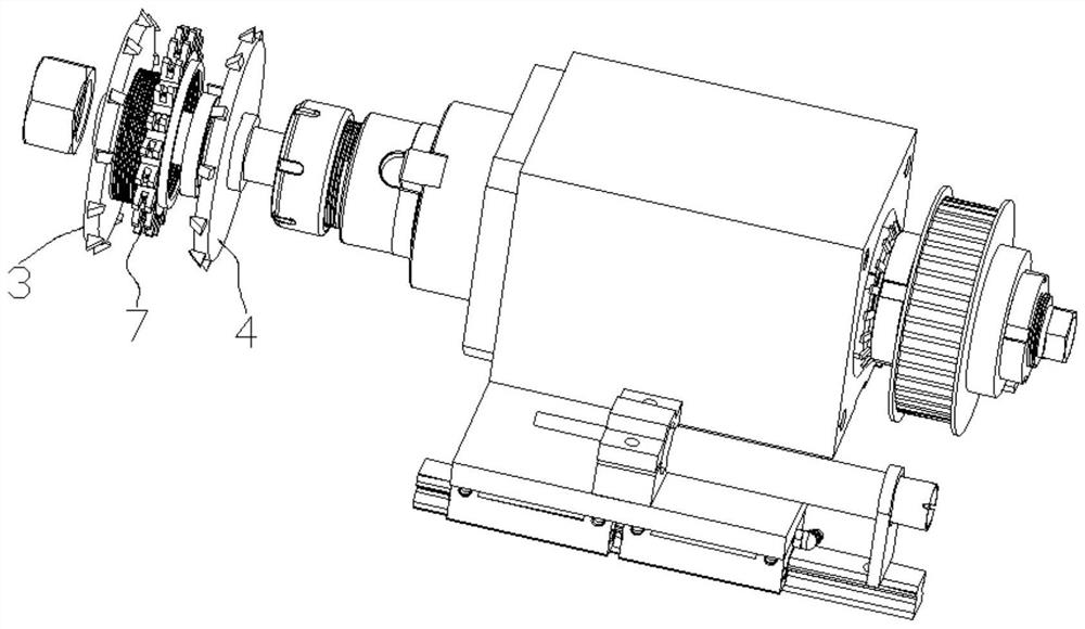
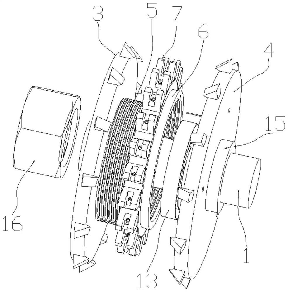
[0028] Example 1, such as Figure 1~2 , 6, a gear chamfering device of the present invention includes a rotating shaft 1, a driving device 2 for driving the rotating shaft 1 to rotate, a frame for installing the driving device 2, a first cutter head 3 and a second cutter head 3 that are in transmission with the rotating shaft 1 Two cutterheads 4, one end of the rotating shaft 1 is connected to the driving device 2, and the other end extends outward in a free state. The first cutter head 3 and the second cutter head 4 are symmetrical to each other, and their outer peripheral surfaces are provided with replaceable cutters. The cutters are triangular in shape and made of hard alloy. The inner side of the cutter extends inward for removing gears. The material of the outer surface, when the gear cutters of the first cutter head 3 and the second cutter head 4 are opposite, so that the first cutter head 3 and the second cutter head 4 are spaced apart to form a chamfering hole for the...

Embodiment 2

[0037] Example 2, such as Figure 7-8 As shown, the difference between this embodiment and Embodiment 1 is that in this embodiment, a liquid bag 20 is provided between the inner side of the follower engagement plate 7 and the outer surface of the second connecting sleeve 6, and the follower engagement plate 7 The inner side and the outer surface of the second connecting sleeve 6 are provided with a locking groove 21 for limiting the position of the liquid bag 20. At the same time, the surface of the second connecting sleeve 6 is provided with a liquid channel 22, and the liquid channel 22 is connected with the joint 23. The liquid bag 20 is in communication, and the outer end surface of the second connection sleeve 6 is provided with a liquid injection port and a liquid discharge port. The liquid injection port and the liquid discharge port are both connected to the liquid passage 22. When used, the follow-up engagement plate 7 and the second connection sleeve 6 are clamped by...


PUM


Abstract

The invention discloses a gear chamfering device, which belongs to the technical field of gear processing, and comprises a rotating shaft, a driving device for driving the rotating shaft to rotate, a rack for mounting the driving device, a first cutter head and a second cutter head, the first cutter head and the second cutter head are in transmission fit with the rotating shaft, and the first cutter head and the second cutter head are mutually symmetrical; serrated cutters of the first cutter head and the second cutter head are opposite to each other, so that the first cutter head and the second cutter head are separated to form a space for chamfering the outer edges of the two sides of a gear; according to the device, the follow-up meshing disc is arranged, when the gear continues to feed after meeting the technological requirements, and the follow-up meshing disc and the second cutter disc rotate relatively, the proximity switch receives an instruction, and the controller controls the driving device to stop; by adopting the device disclosed by the invention, the technical problem that the chamfering precision is low due to the fact that the gear feeding is judged by adopting the manual proficiency degree in a traditional mode is solved.

Description

technical field [0001] The invention belongs to the technical field of gear processing, and in particular relates to a gear chamfering device. Background technique [0002] With the continuous advancement of technology, gears are developing towards a more scientific and precise level. Mechanical manufacturing has higher and higher requirements for gears in terms of precision, bearing capacity, noise and service life. The use of gear chamfering technology is reducing Gear noise plays an important role in improving the service life of gears. When chamfering the edge of a gear, some existing large-scale gear chamfering equipment aligns the chamfering knife with the gear, and then displaces the gear towards the direction of the gear knife through a transmission mechanism to realize chamfering. Most of the cutting tools are judged by manual proficiency, resulting in low precision and poor uniformity of chamfering. Contents of the invention [0003] In view of this, the object...

Claims


Application Information

Patent Timeline
Patent Type & Authority Applications(China)
IPC IPC(8): B23F19/10
CPCB23F19/10Y02P70/10
Inventor 胡廷元周维琴向曾义杨芬徐春燕王宠施勇朱帅
Owner CHONGQING JUJIA MACHINERY
Why Eureka
Try Eureka