Tube turning clamping and shrinking device

A shrinking device and clamping technology, applied in the direction of pipe supports, pipes/pipe joints/pipes, mechanical equipment, etc., can solve the problems of cumbersome procedures and high labor intensity, and achieve the effect of simple operation and shortening of bending time.

Inactive Publication Date: 2009-06-10
MCC TIANGONG GROUP
View PDF0 Cites 0 Cited by
  • Summary
  • Abstract
  • Description
  • Claims
  • Application Information

AI Technical Summary

Problems solved by technology

This kind of clamping device can only realize one kind of movement, that is, clamping, and a special operating handle or operating switch must be provided when this type of clamping device works. Other mechanical mechanisms, the process is cumbersome and labor-intensive

Method used


Image

  • Tube turning clamping and shrinking device
  • Tube turning clamping and shrinking device
  • Tube turning clamping and shrinking device

Examples


Embodiment Construction

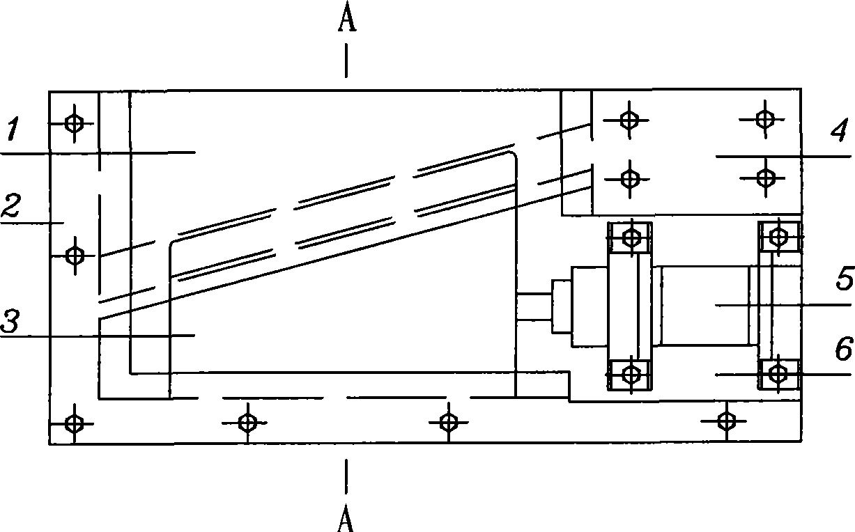
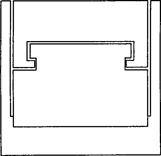
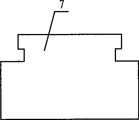
[0012] Such as figure 1 , 2 Shown: a pipe rotary clamping and shrinking device, the two sides of the translation wedge block 1 are completely contained in the guide grooves 2 and 4, so that the wedge block can only be translated in the direction of the slot under the action of external force sports. The main prominent point of this patent is that the embedded wedge-shaped block 3 is embedded in the wedge-shaped block 1, which is equivalent to that the wedge-shaped block 1 provides an embedded guiding sliding track for the wedge-shaped block 3. The upper and lower sides of the hydraulic cylinder 5 are respectively equipped with a lower cover plate, which is fixed on the lower cover plate 6 by screws. One end of the embedded wedge-shaped block 3 is fixed on the hydraulic cylinder 5, and the other end surface is contained in the guide groove 2, that is, The movement trajectory of the wedge-shaped block 3 is fixed, which is the same as that of the hydraulic cylinder 5. When the ...


PUM


Abstract

The invention relates to a pipeline turning clamping and contracting device which consists of a translational inclined wedge-shaped block, two guide grooves and a hydraulic cylinder. The two sides of the translational inclined wedge-shaped block are respectively contained in the two guide grooves, and the translational inclined wedge-shaped block is embedded with an embedded inclined wedge-shaped block which can slide in the translational inclined wedge-shaped block; the hydraulic cylinder is fixed on a lower cover board, one end surface of the embedded inclined wedge-shaped block is fixed on the hydraulic cylinder, and the other end surface is contained in one guide groove. The device has the following advantages: the invention relates to a pipeline clamping and contracting device, in which the inclined wedge-shaped block is pulled and pushed hydraulically, the clamping and contracting of the pipeline is controlled by the hydraulic cylinder, and any other external force is not needed. A special bend operation button or handle is not needed to set, thus leading to simple operation and shortening the pipeline bending time greatly.

Description

Technical field: [0001] The invention belongs to equipment used in the construction of small-diameter pipelines in the metallurgical industry, in particular to a clamping and shrinking device for pipeline rotation. Background technique: [0002] At present, the pipe rotary clamping device used in the construction of medium and small diameter pipelines in the metallurgical industry generally uses fluid as power to push the wedge-shaped block to achieve the purpose of clamping. This kind of clamping device can only realize one kind of movement, that is, clamping, and a special operating handle or operating switch must be provided when this type of clamping device works. Other mechanical mechanisms have cumbersome procedures and high labor intensity. Invention content: [0003] The purpose of the present invention is to overcome the shortcomings of the above-mentioned prior art, and provide a pipe rotary clamping and shrinking device, which can realize clamping and shrinking...

Claims


Application Information

Patent Timeline
Patent Type & Authority Applications(China)
IPC IPC(8): F16L3/00
Inventor 刘巨才张溪波
Owner MCC TIANGONG GROUP
Why Eureka
Try Eureka