High and low voltage changeover circuit

A high and low voltage conversion and circuit technology, applied in the direction of adjusting electrical variables, control/regulation systems, instruments, etc.

Active Publication Date: 2009-06-17
SHENZHEN SUNMOON MICROELECTRONICS
View PDF0 Cites 5 Cited by
  • Summary
  • Abstract
  • Description
  • Claims
  • Application Information

AI Technical Summary

Problems solved by technology

[0004] The purpose of the present invention is to solve the problems caused by the use of zener tubes in high-voltage and low-voltage conversion circuits, and to provide a circuit that realizes the conversion function from high voltage to low voltage without using a voltage-stabilizing zener tube in a standard foundry process

Method used


Image

  • High and low voltage changeover circuit
  • High and low voltage changeover circuit
  • High and low voltage changeover circuit

Examples


Embodiment Construction

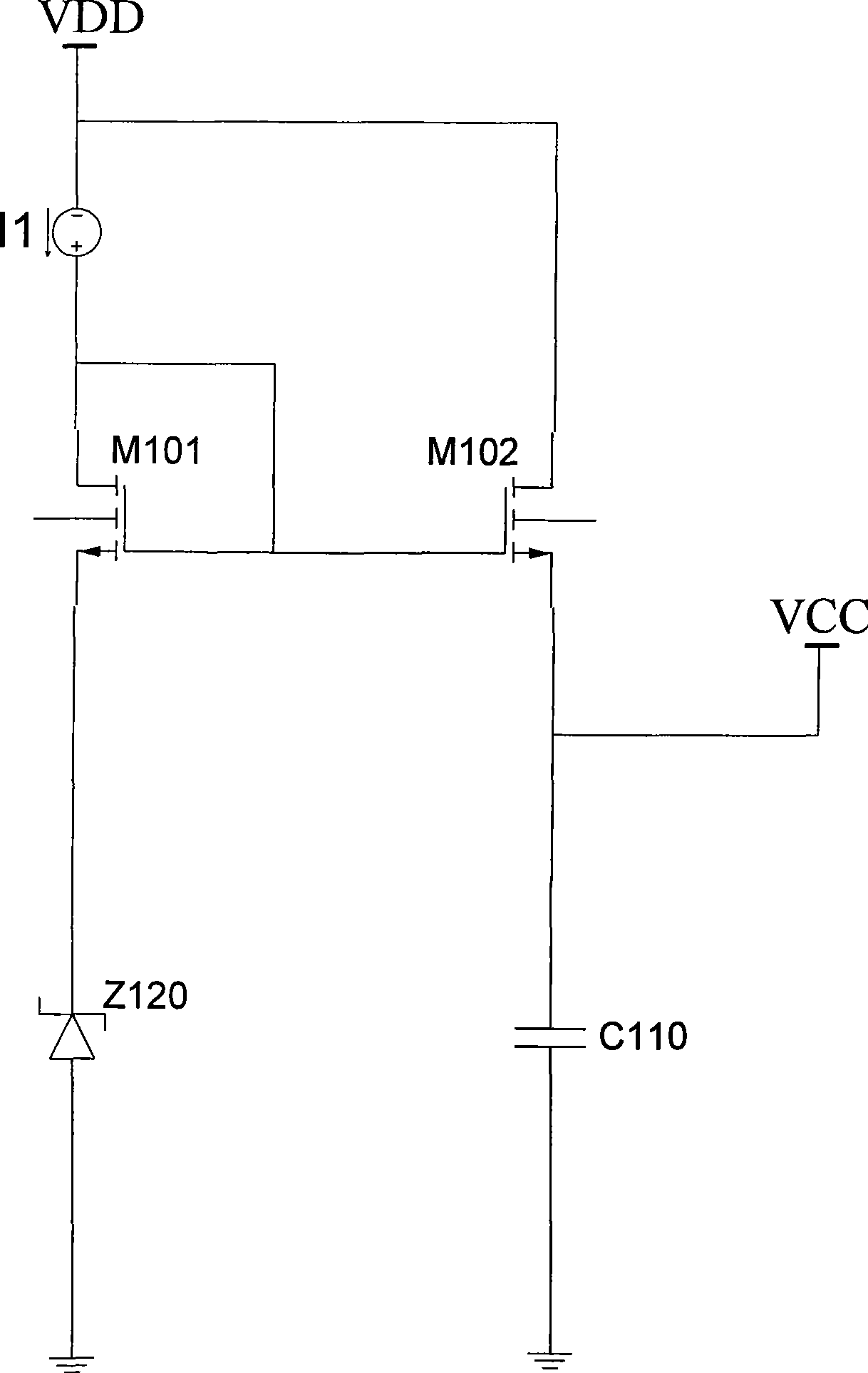
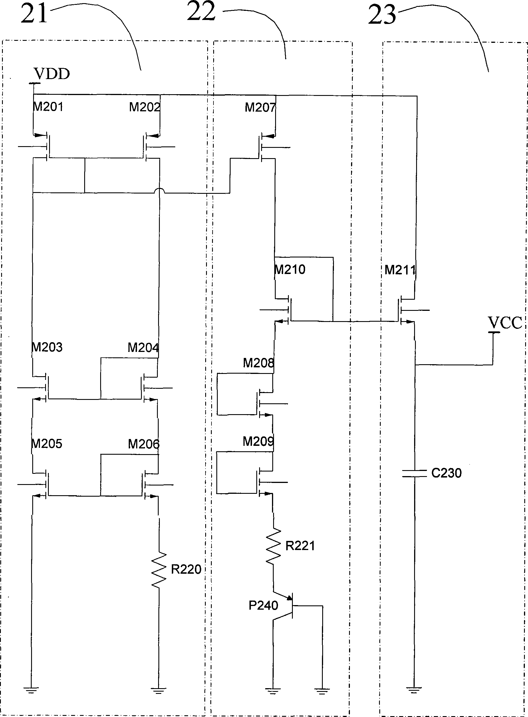
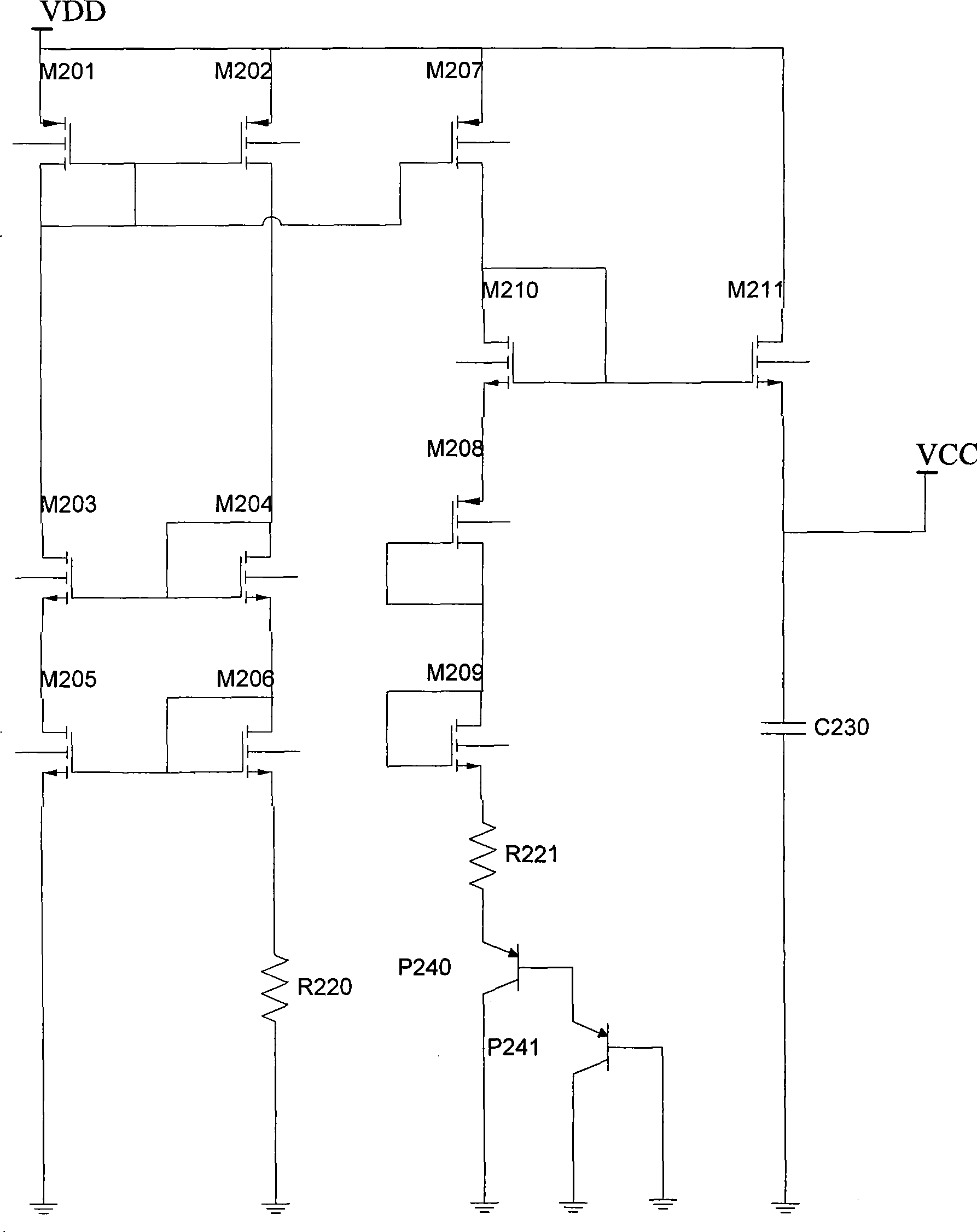
[0017] Such as figure 2 A high-voltage and low-voltage conversion circuit shown includes a reference current generation circuit 21 , a low-voltage generation circuit 22 and an output voltage stabilization circuit 23 . Wherein, the reference current generation circuit 21 provides a reference current for the low voltage generation circuit 22; the low voltage generation circuit includes a parasitic PNP, a compensation resistor and a low voltage MOS transistor, and the parasitic PNP, compensation resistor and a low voltage MOS transistor provide a stable drive for the output voltage stabilizing circuit Voltage; the driving voltage is output by the first current mirror and the stable low-voltage VCC through the voltage stabilizing capacitor in the output voltage stabilizing circuit.

[0018] The first current mirror includes a tenth NMOS transistor M210 on the low voltage generating circuit 22 and an eleventh NMOS transistor M211 on the output voltage stabilizing circuit 23 . Whe...


PUM


Abstract

The invention discloses a high-low pressure converting circuit which belongs to the integrated circuit technique field. The high-low voltage converting circuit includes a basic current generating circuit, a low pressure generating circuit and an output voltage regulator circuit; wherein, the basic current generating circuit provides current for the low pressure generating circuit; the low pressure generating circuit includes an autoeciousness PNP, a compensating resistor and a low pressure MOS pipe, an autoeciousness PNP, the autoeciousness PNP, the compensating resistor and the low pressure MOS pipe provide stable driving voltage for the output voltage regulator circuit; the driving voltage outputs stable low voltage on the output voltage regulator circuit through a stabilized voltage capacitance through a first current mirror. The high-low voltage converting circuit uses standard apparatus such as MOS pipe, audion, resistor and capacitance without Zener diode, and needs not extra cost, reduces chip cost and modulation cost.

Description

technical field [0001] The invention belongs to the technical field of integrated circuits, and in particular relates to a high and low voltage conversion circuit. Background technique [0002] In the field of integrated circuit manufacturing, the latest technology is first applied to the production and design of digital chips, and then some resistors, capacitors, and parasitic transistors required by analog chips are added to the technology. However, the analog process provided by the electronic foundry cannot provide the devices required by some special analog circuits. One of the devices is the Zener tube. In the design of switching power supply integrated circuits for voltage conversion. [0003] If the production process provides the zener tube, it can be figure 1 The shown method realizes the high-voltage and low-voltage conversion inside the chip. Among them, the reference current is provided by the current source I1, and the input voltage is VDD. After the Zener t...

Claims


Application Information

Patent Timeline
Patent Type & Authority Applications(China)
IPC IPC(8): G05F3/26
Inventor 王乐康李照华王蒙
Owner SHENZHEN SUNMOON MICROELECTRONICS
Why Eureka
Try Eureka