Jet former

A technology of former and jet, which can be used in indoor sanitary pipe installations, water supply installations, buildings, etc., and can solve problems such as high noise

Active Publication Date: 2009-09-30
NEOPERL
View PDF0 Cites 2 Cited by
  • Summary
  • Abstract
  • Description
  • Claims
  • Application Information

AI Technical Summary

Problems solved by technology

However, the water jets emerging from such water valves only initially have the desired jet band, before the water jet has already contracted after a relatively short free path into a noisy, uncontrolled, non-circular jet. shape

Method used


Image

  • Jet former
  • Jet former
  • Jet former

Examples


Embodiment Construction

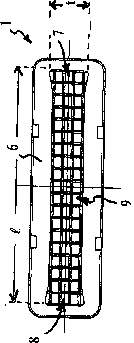
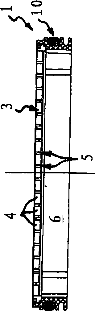
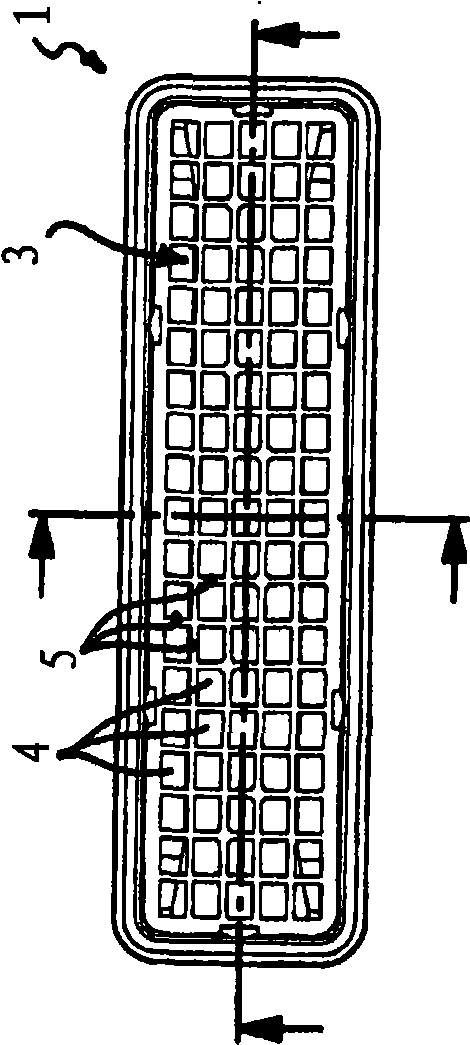
[0023] exist Figures 1 to 7 A jet former 1 is shown in a different view. From Figure 7 It can be clearly seen in the transverse sectional view of , that the jet shaper 1 can be installed in the water outlet 2 of the sanitary water valve. The jet former 1 has a homogenizer 3 which forms the inflow-side end face of the jet former 1 . The homogenizer 3 has a plurality of throughflow openings 4 which are each surrounded and delimited by a fluid-guiding wall 5 . From figure 1 , 3 And it can be clearly seen from 5 to 7 that the fluid-guiding wall 5 is formed as a grid-like structure.

[0024] exist figure 1 As can be seen in , the jet former 1 has a jet width l greater than the jet depth t in order to generate a smooth water jet strip. From Figure 4 and 7 It can be seen in the transverse sectional view of the homogenizer 3 that a fluid guide 6 is connected downstream of the homogenizer 3, which tapers nozzle-like at least in some regions in the flow direction. On both s...


PUM


Abstract

The former (1) has a homogenizing device with a set of passage holes that are limited by a flow guiding wall, where the former has a larger stream width compared to stream depth (t) for producing a flat water flow volume. A flow guide (6) is provided upstream or downstream and narrows in a partial area in a flow direction. The flow guide has edge areas (7, 8) with a larger flow cross section relative to a longitudinal middle area (9), where the edge areas extend in both sides of the guide in a longitudinally extending manner.

Description

technical field [0001] The invention relates to a jet former, which is arranged in the water outlet of a sanitary water valve and has at least one homogenizer with a plurality of through-holes which are each surrounded and delimited by a fluid-guiding wall. Background technique [0002] In the water outlet of conventional sanitary water valves, a jet former designed as a jet regulator is usually installed, which is intended to form the incoming water flow into a homogeneous, non-splashing water jet. For this purpose, known jet regulators have a homogenizer which has a honeycomb or grid-like or net-like structure with a plurality of flow holes which are each surrounded by flow-guiding walls limited. In this case, further functional units may optionally be connected upstream of the homogenizer on the inflow side. [0003] Known jet regulators generally have a circular flow cross-section adapted to the water valve. But people have been working hard to design such water valve...

Claims


Application Information

Patent Timeline
Patent Type & Authority Applications(China)
IPC IPC(8): E03C1/08
CPCE03C1/08
Inventor F·维尔德方
Owner NEOPERL
Why Eureka
Try Eureka