
Plate stretch-forming machine
A drawing machine and plate technology, which is applied in the field of mechanical engineering, can solve the problems of uneven distribution of tensile stress and tensile strain of parts, reduced material utilization, and expensive manufacturing costs, so as to improve material utilization, reduce manufacturing costs, and reduce load. Path reasonable effect
- Summary
- Abstract
- Description
- Claims
- Application Information
AI Technical Summary
Problems solved by technology
Method used
Image


Examples
Embodiment Construction
[0042] The specific content and working process of the present invention will be further described below in conjunction with the embodiments shown in the accompanying drawings.
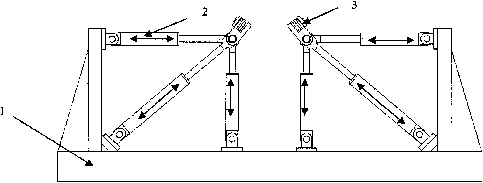
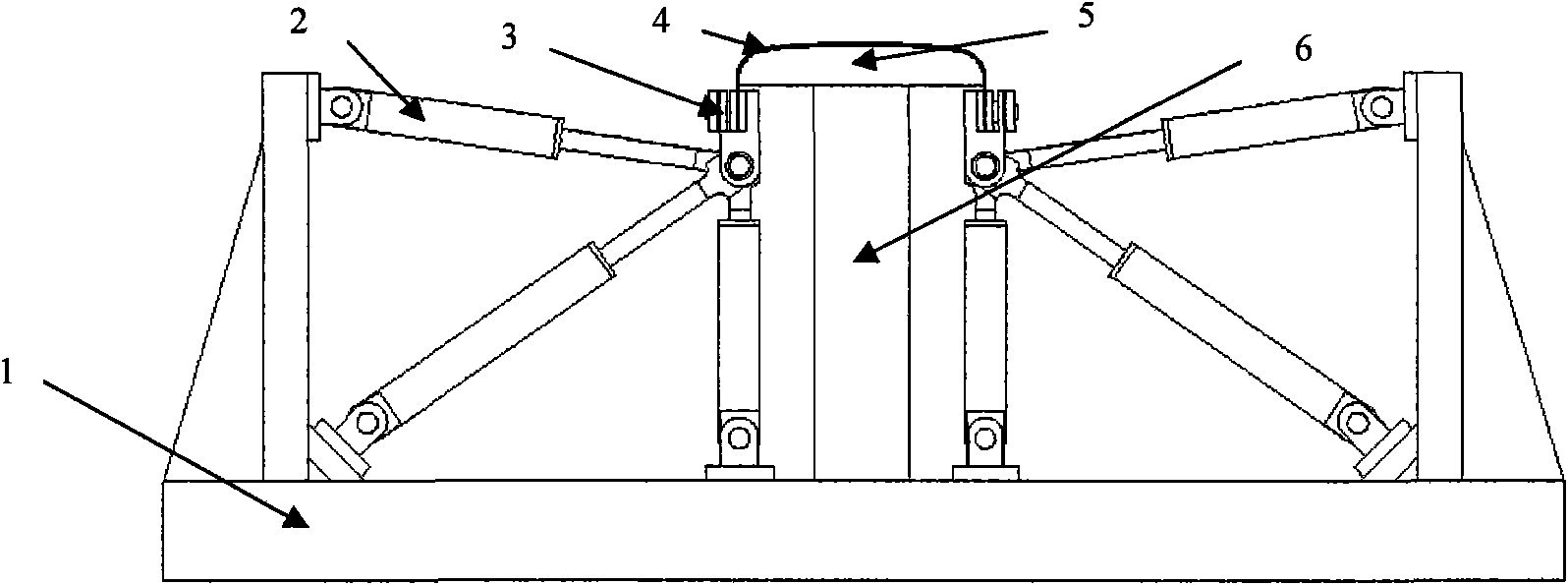
[0043] Fig. 1 is a schematic diagram of a drawing machine, which is mainly composed of a frame 1 and a row of five pulling mechanisms and clamping mechanisms 3 on the left and right sides of the frame 1. The material pulling mechanism is made up of three hydraulic cylinders 2, one is arranged horizontally, one is arranged vertically, and the other is arranged obliquely. One end of the hydraulic cylinder 2 is respectively hinged with the frame 1, and the other end is jointly hinged with the clamping mechanism 3. By changing the hydraulic pressure of the hydraulic cylinder 2, the stroke of the hydraulic cylinder 2 can be changed, and the angle between the hydraulic cylinders 2 can also be changed, thereby changing the position and the pulling direction of the clamping mechanism 3. The hydraulic pressur...
PUM
 Abstract
Description
Claims
Application Information