Pneumatic nozzle of variable geometry turbocharger (VGT)

A technology of turbocharger and pneumatic nozzle, applied in the field of turbocharger nozzle and pneumatic nozzle, can solve the problems of poor effect, small exhaust flow, unfavorable exhaust pressure, etc., so as to improve the response characteristics and increase the supercharging ratio. , Efficient matching effect

Active Publication Date: 2011-07-20
KANGYUE TECH
View PDF0 Cites 1 Cited by
  • Summary
  • Abstract
  • Description
  • Claims
  • Application Information

AI Technical Summary

Problems solved by technology

[0004] The variable geometry turbocharger with composite nozzles is currently used. In practical applications, it is found that the variable geometry turbocharger still has some shortcomings in terms of performance matching. The speed of modern engines is getting higher and higher, and the matching range is also increasing. wide, the current variable geometry supercharger is difficult to maintain high efficiency in the whole operating conditions
The variable nozzle turbocharger is matched with the calibration points to ensure that the flow capacity of the supercharger meets the requirements. The low-speed working condition is completely adjusted by the nozzle blades. The adjustment range is too wide, and it is difficult to ensure good performance in a wide range. effect and high turbine efficiency; the composite nozzle is matched with the high torque point, the nozzle vane is closed between the calibration point and the high torque point, and under low speed conditions, the nozzle moving vane is opened, which reduces the adjustment range of the nozzle vane. It is beneficial to realize optimal control within the entire adjustment range, but the calibration point needs to be equipped with auxiliary adjustment devices such as air release valves
In addition, the above-mentioned two kinds of adjustable nozzle turbochargers all rely entirely on reducing the nozzle flow area to increase the intake pressure of the turbine under low working conditions, so that the energy available to the turbine can be increased to achieve the purpose of increasing the output work of the turbine. The exhaust flow rate is small under low-speed conditions, and the effect of simply increasing the exhaust pressure to increase the turbine output work is relatively poor, and the excessively high exhaust pressure is not conducive to the improvement of the engine's working efficiency

Method used


Image

  • Pneumatic nozzle of variable geometry turbocharger (VGT)
  • Pneumatic nozzle of variable geometry turbocharger (VGT)
  • Pneumatic nozzle of variable geometry turbocharger (VGT)

Examples


Embodiment

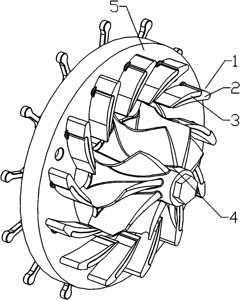
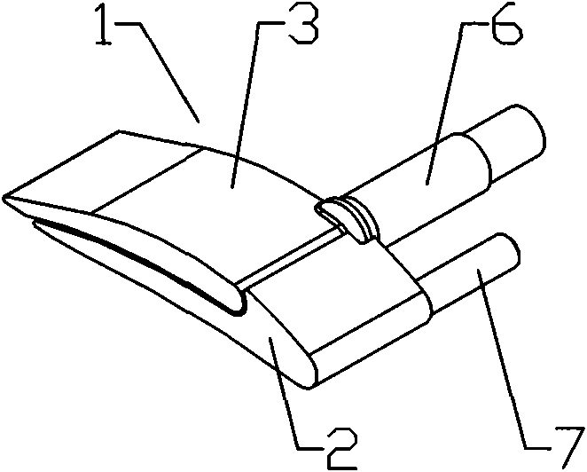
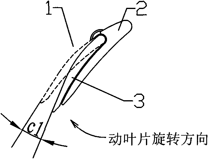
[0028] Example: such as Figure 4 , Figure 5 with Image 6 As shown, the aerodynamic nozzle of the variable geometry turbocharger includes an aerodynamic nozzle support plate 8 and a power turbine 15 coaxially connected with the aerodynamic nozzle support plate 8, and the aerodynamic nozzle support plate 8 is arranged on the surface of the power turbine 15 side There are thirteen pneumatic nozzle blades 12. The shape of the pneumatic nozzle blades 12 is arc-shaped. On the other surface of the pneumatic nozzle support plate 8, a shift fork plate 10 is arranged. The shift fork 11 is provided, the pneumatic nozzle blade 12 includes the pneumatic nozzle moving blade 13 and the pneumatic nozzle stationary blade 14, the pneumatic nozzle moving blade 13 includes an outer arc surface 131 and an inner arc surface 132, and the inner arc surface 132 forms a groove 24, the pneumatic nozzle The nozzle stationary vane 14 is located in the groove 24, the surface matching the pneumatic noz...


PUM


Abstract

The invention relates to a pneumatic nozzle of a variable geometry turbocharger (VGT), comprising a pneumatic nozzle supporting disk, and a plurality of pneumatic nozzle blades which are arranged on the pneumatic nozzle supporting disk, wherein, the pneumatic nozzle blades comprise pneumatic nozzle moving blades and pneumatic nozzle stationary blades, and the pneumatic nozzle stationary blades are internally provided with a flow channel. During operation of the turbocharger, the width of the air flow channel among the adjacent pneumatic nozzle blades can be adjusted by adjusting the rotation angle of the pneumatic nozzle moving blades so as to adjust the pressure ratio of the turbocharger so that the turbocharger is matched with the working condition of an engine; and when adequate pressurizing ratio can not be provided in the event that the working condition of the engine is further reduced and the width of the air flow channel among the adjacent pneumatic nozzle blades is adjusted to the minimum, supplementary gas can be sprayed by a connecting pipe, the channel on the pneumatic nozzle supporting disk and the flow channel on the pneumatic nozzle stationary blades so as to improve the pressure ratio of the turbocharger so that the turbocharger is matched with the working condition of the engine.

Description

technical field [0001] The invention relates to a turbocharger nozzle, in particular to an aerodynamic nozzle for a variable geometry turbocharger, which belongs to the field of internal combustion engines. Background technique [0002] The turbocharger uses the exhaust gas discharged from the engine to flow into the turbine casing of the turbocharger according to a certain route to drive the turbine, and drives the compressor impeller coaxial with the turbine to rotate at high speed. It is compressed into the cylinder of the engine. Due to the high density of the compressed air, the air supply of the engine is increased, more fuel can be completely burned, the power of the engine is improved, and the consumption of fuel is saved. At the same time, due to the full combustion of the fuel, Reduce CO, HC, NO in engine exhaust gas X As well as the content of harmful substances such as PM, the noise of the engine is also simultaneously reduced by guiding the exhaust gas flow of ...

Claims


Application Information

Patent Timeline
Patent Type & Authority Patents(China)
IPC IPC(8): F01D9/02
Inventor 王航桑悟海李延昭朱志富李永泰信效芬
Owner KANGYUE TECH
Why Eureka
Try Eureka