Grid modulator

A grid and voltage regulation control technology, which is applied to X-ray equipment, electrical components, etc., can solve the problems of inconvenient realization of voltage transformation, the limitation of grid modulation module volume, and the inability to be large, and achieves simple structure and clear logic. , the effect of preventing the flow of charge

Active Publication Date: 2010-06-23
NEUSOFT MEDICAL SYST CO LTD +1
View PDF0 Cites 12 Cited by
  • Summary
  • Abstract
  • Description
  • Claims
  • Application Information

AI Technical Summary

Problems solved by technology

Since it is used in medical equipment, there is a corresponding limitation on the size of the grid modulation module, which cannot be as large as in the industry or military
However, the control system of the current grid modulation device is relatively complicated, the volume is large, and it is not convenient to realize the variable voltage regulation.

Method used


Image

  • Grid modulator
  • Grid modulator
  • Grid modulator

Examples


Embodiment Construction

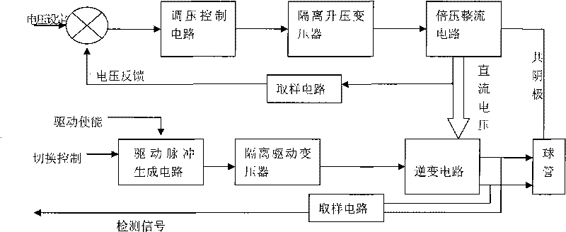
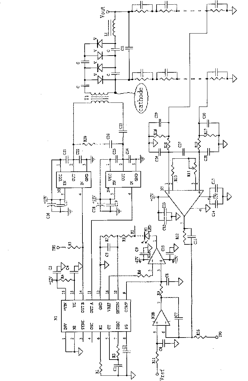
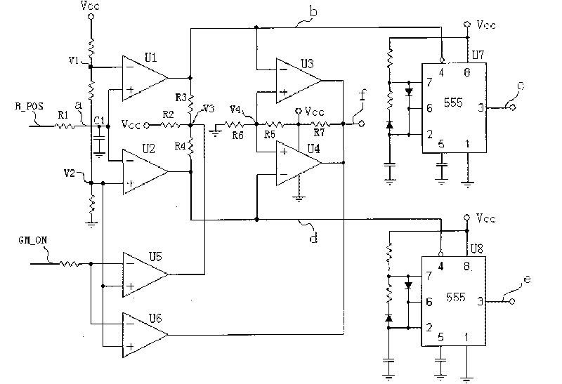
[0019] The invention is developed aiming at the working characteristics of the medical bulb grid system. The grid of the medical bulb is composed of two grid plates. The reference source of the grid voltage is the cathode of the bulb. When working, the required voltage is added to the grid to form a deflection electric field. This voltage can be a DC voltage or a square wave voltage. The working characteristics of the grid modulation device are high voltage, low current, and low power, and meet the power requirements as much as possible while reducing the module volume. The present invention is based on the requirement of using a PWM modulation method to control a wider voltage output range. The voltage range of the cathode of the reference bulb is 0-3000V, and the output frequency of the square wave voltage is 0-3000HZ. The driving requirements of the full range are realized by driving the pulse generation circuit, and the insulation requirements of the low-voltage part and ...


PUM


Abstract

The invention relates to a grid modulator, which is installed in to a high voltage generator and includes a voltage controlling circuit, an isolating boosting transformer, a voltage doubling rectifying circuit, a drive pulse generation circuit, an isolating drive transformer, an inverter circuit, and a sampling circuit. The voltage controlling circuit automatically adjusts and outputs a voltage value to the isolating boosting transformer according to a set voltage value; the primary winding of the isolating boosting transformer is connected with the output end of the voltage controlling circuit to boost the voltage outputted by the voltage controlling circuit; the voltage doubling rectifying circuit implements doubling rectifying on the voltage boosted by the isolating boosting transformer; the drive pulse generation circuit receives the command of the control part of the high voltage generator and outputs a drive pulse; the primary winding of the isolating drive transformer is connected with the output end of the drive pulse generation circuit; the secondary winding of the isolating drive transformer is connected with the inverter circuit; the inverter circuit inverts a DC voltage formed by the voltage doubling rectifying circuit; the sampling circuit samples a voltage signal and respectively feeds back the voltage signal to the voltage controlling circuit and the control part of the high voltage generator. The grid modulator has simple structure and self-cutting function, and can meet insulating requirements.

Description

technical field [0001] The invention relates to a medical high-voltage generator, in particular to a grid modulation device in the medical high-voltage generator. Background technique [0002] In the medical field, more and more CT products adopt the "flying focus" technology. The advantages of the flying focus technology are two points: 1. Focus switching is beneficial to the heat dissipation of the tube, thus protecting the anode target surface. 2. Flying focus technology can obtain double data and increase the amount of image information. There are usually two ways to realize "flying focus", one is to use magnetic deflection technology, and the other is to use electric field deflection technology to realize. There are two grid plates inside the tube that uses electric field deflection technology to realize the flying focus. The reference point of the grid voltage is the cathode of the tube. When working, add the required voltage to the grid. This voltage can be a DC volt...

Claims


Application Information

Patent Timeline
Patent Type & Authority Applications(China)
IPC IPC(8): H05G1/10H05G1/32
Inventor 付国辉
Owner NEUSOFT MEDICAL SYST CO LTD
Why Eureka
Try Eureka