Flat plate reflective array antenna

A flat-panel reflection and array antenna technology, which is applied to antennas, radiating unit covers, electrical components, etc., can solve the problems of restricting popularization and development, troublesome installation and carrying, and achieve the effects of avoiding feed loss, easy installation, and simplified design process

Active Publication Date: 2013-03-20
COMBA TELECOM SYST (GUANGZHOU) LTD +1
View PDF0 Cites 0 Cited by
  • Summary
  • Abstract
  • Description
  • Claims
  • Application Information

AI Technical Summary

Problems solved by technology

Although the reflector antenna omits the complex feed network, the feed placed at the focal point in front of the reflector makes the overall profile height of the antenna several times the working wavelength
Therefore, its three-dimensional structure causes installation and carrying trouble
[0005] In summary, although the existing two high-gain antennas can achieve higher gain, their respective shortcomings seriously restrict their own promotion and development.

Method used


Image

  • Flat plate reflective array antenna
  • Flat plate reflective array antenna
  • Flat plate reflective array antenna

Examples


Embodiment Construction

[0020] The present invention will be further described below in conjunction with the drawings and embodiments.

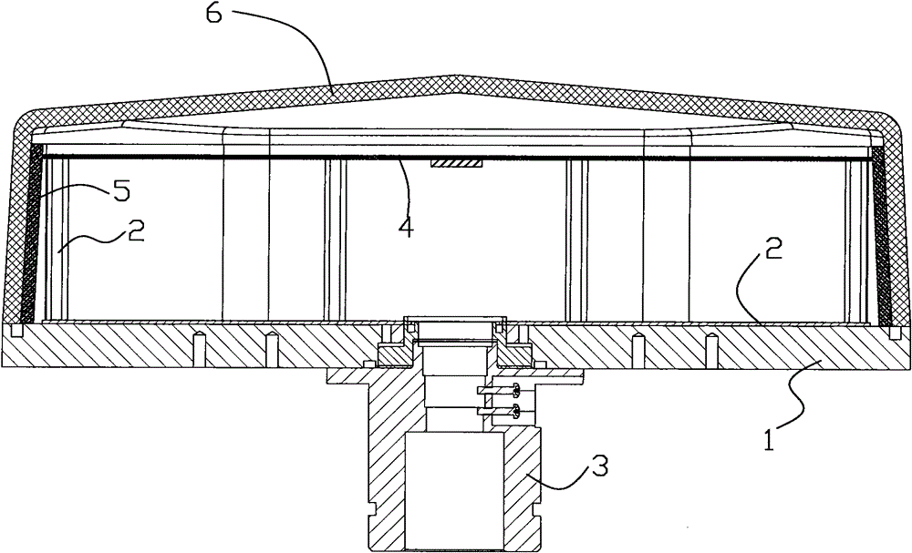
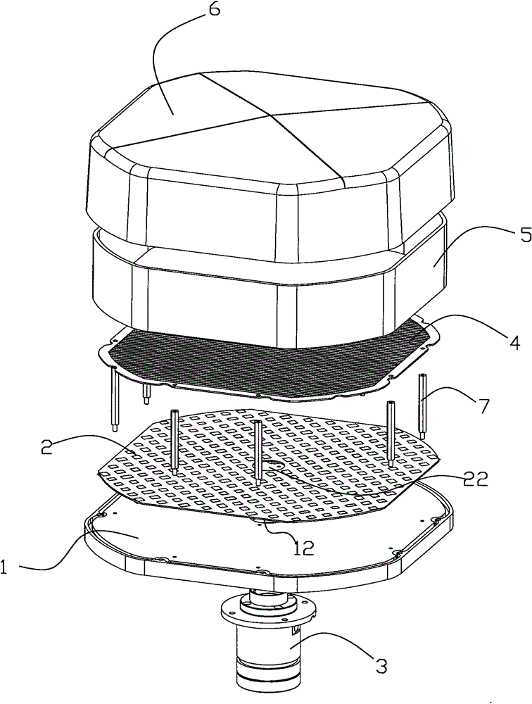
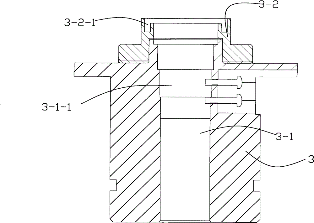
[0021] reference Figure 1-Figure 7 , The present invention provides a flat reflector array antenna, which includes a metal base plate 1, a dielectric plate 2 mounted on the top of the metal base plate 1 and parallel to the metal base plate 1, supported on the dielectric plate 2 through a supporting column 7 and connected with The dielectric plate 2 and the metal base plate 1 are parallel to the polarized grid plate 4 separated by a certain distance, and are installed on the periphery of the metal base plate 1 to surround the dielectric plate 2 and the polarized grid plate 4. The radome 6 which is buckled and installed with the metal bottom plate 1 so as to surround the dielectric plate 2, the polarization grid 4 and the absorbing material border 5, and is installed at the bottom center of the metal bottom plate 1 and passes through the The metal bottom plate 1 and the...


PUM


Abstract

The invention relates to a flat plate reflective array antenna which comprises the following components: a metallic bottom plate, a dielectric plate, a polarized grid plate, wave absorbing material surrounding edges, an antenna cover and a feed source, wherein the dielectric plate is installed on the top of the metallic bottom plate and is parallel with the metallic bottom plate; the polarized grid plate is supported on the dielectric plate through a supporting pillar, is parallel with the dielectric plate and the metallic bottom plate, and has a certain distance to the dielectric plate and the metallic bottom plate; the wave absorbing material surrounding edges are installed at the periphery of the metallic bottom plate so as to surround the dielectric plate and the polarized grid plate; the antenna cover is buckled with the metallic bottom plate so as to surround the dielectric plate, the polarized grid plate and the wave absorbing material surrounding edges; and the feed source is installed at the center of the bottom of the metallic bottom plate and passes through the metallic bottom plate and the dielectric plate. The antenna has the advantages of simple feeding, high gain, good directional diagram envelope, wide frequency band, small volume, light weight, easy installation and the like, and can be used for the fields of microwave communication, satellite communication and the like.

Description

【Technical Field】 [0001] The invention relates to a high-gain antenna, in particular to a flat reflector array antenna. 【Background technique】 [0002] There are mainly two types of existing high-gain antennas, one is an array antenna, and the other is a reflector antenna. [0003] The array antenna is a combination of multiple antennas that are distributed according to a certain amplitude and phase. This combination of antennas excites multiple radiating elements to achieve high signal gain. The excitation amplitude and phase of each radiating unit are controlled by the feed network. Generally, the higher the gain requirement of the antenna signal, the more the number of radiating elements required, which leads to the more complicated the feeding network. Complicated feeder network will increase the difficulty of electrical design and physical layout on the one hand, leading to adverse effects on structural design and weight. On the other hand, the complex feed loss will reduce ...

Claims


Application Information

Patent Timeline
Patent Type & Authority Patents(China)
IPC IPC(8): H01Q19/185H01Q15/22H01Q17/00H01Q1/42
Inventor 吴知航王岩刘素芹符道临谢庆南潘军
Owner COMBA TELECOM SYST (GUANGZHOU) LTD
Why Eureka
Try Eureka