Display panel, display method, display device and color rendition method thereof

A display method and display panel technology, applied to identification devices, static indicators, instruments, etc., can solve problems such as high manufacturing costs and complex structure of display panels, and achieve the effects of reducing production costs, simple structure, and reducing manufacturing accuracy

Inactive Publication Date: 2010-10-27
季中
View PDF6 Cites 16 Cited by
  • Summary
  • Abstract
  • Description
  • Claims
  • Application Information

AI Technical Summary

Problems solved by technology

The above method realizes the display of any color through the spatial compounding of three display units, which makes each pixel need to be composed of three display units, three different display units are arranged alternately, and there are three different scanning lines and three different scanning lines. The data lines used to control the colors displayed by the three display units lead to a complex structure of the display panel and high manufacturing costs

Method used


Image

  • Display panel, display method, display device and color rendition method thereof
  • Display panel, display method, display device and color rendition method thereof
  • Display panel, display method, display device and color rendition method thereof

Examples


Embodiment 1

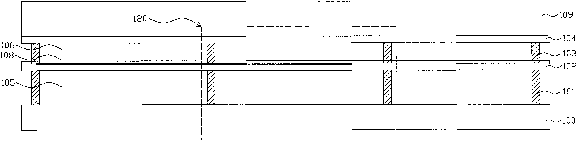
[0102] The following is attached Figure 3 to Figure 13 An embodiment of the display panel is described in detail. The display panel in this embodiment is reflective, that is, the light source and the observer are located on the same side of the display panel.

[0103] image 3 It is a schematic diagram of the structure of the display panel. A dotted line on the display panel represents a pixel 120 displaying a color, and an array of a plurality of such pixels displaying a color is arranged repeatedly to form a display panel. The display panel includes: a substrate 100, a first support layer 101 on the substrate 100, a first reflective layer substrate 102 on the first support layer 101, and a first reflective layer with a specific light transmittance coated on the first reflective layer substrate 102. Layer 108, the second support layer 103 on the first reflective layer 108, the transparent film layer 109 of the second reflective layer 104 coated with a specific light trans...

Embodiment 2

[0149] Figure 14 It is a schematic diagram of the display device described in this embodiment, including: a control unit 201, and a display panel 202; wherein, the control unit 201 is used to drive the display panel 202 and transmit data signals received from the outside of the display device to the display panel 202; the display panel 202 is used to display images according to the received data signal under the drive of the control unit 201. The display panel 202 may be any display panel in Embodiment 1, which will not be repeated here.

[0150] The control unit 201 is composed of a source driver integrated circuit and an address driver integrated circuit (not shown in the figure). The source driver integrated circuit is connected to the source of each TFT of the pixel array on the display panel through a data line, thereby transmitting a data signal to the pixel; and the address driver integrated circuit is connected to each TFT of the pixel array on the display panel thro...

Embodiment 3

[0167] Figure 16 It is a schematic structural diagram of the display panel described in Embodiment 1. Figure 17 to Figure 19 It is a schematic diagram of embossing the first reflective layer in this embodiment. The figure only shows a schematic diagram of embossing one reflective unit in the first reflective layer. In this embodiment, the manufacturing method of the provided display panel is described in detail by taking the manufacturing of the display panel mentioned in the first embodiment as an example. Described method specifically comprises:

[0168] Step A: If Figure 16 As shown, a substrate 100 is provided; the substrate 100 can be a driving substrate with a display driving circuit pattern engraved in advance, or a ready-made driving substrate of an active matrix liquid crystal display (AMLCD). The substrate 100 is provided with an electrode array and wiring. If the active matrix liquid crystal display substrate 100 is used, the substrate is provided with an ar...


PUM


Abstract

The invention provides a display panel, which comprises a base plate. The base plate has a first reflecting layer and a second reflecting layer with specific light transmittance. The first reflecting layer comprises a reflecting unit array. Each reflecting unit comprises a reflecting plate which can continuously move along a direction perpendicular to the first reflecting layer, and a supporting beam connected with the reflecting plate and a connecting part. The invention additionally provides a display method, a display device and a color rendition method thereof. The display panel synthesizes color through time sequence color without distinguishing pixel color, the manufacturing process is only one third of the manufacturing process of a traditional display panel manufacturing method, the structure is simple and the manufacturing cost is low. The display device can compensate color drift caused by manufacturing error, the task of accurately realizing color rendition is transferred to the peripheral circuit of the display panel from the manufacturing process, and thereby the requirement on the precision of the manufacturing process is reduced.

Description

technical field [0001] The invention relates to the technical field of flat panel display, in particular to a display panel and a display method thereof, a display device and a color restoration method thereof. Background technique [0002] Flat panel displays have developed rapidly in recent years due to their small size and light weight. Reflective flat-panel displays use natural light from the outside to form reflected light on the display panel without using a backlight, so they consume less power and can be used directly under strong light, especially suitable for mobile phones and personal digital assistants (PDAs). , portable computers and other portable products. [0003] At present, the display principles of reflective flat panel display technology include: the principle of electrophoresis or electrowetting, the principle of bistable liquid crystal light diffraction, and the principle of light interference. The reflective flat panel display based on the principle ...

Claims


Application Information

Patent Timeline
Patent Type & Authority Applications(China)
IPC IPC(8): G09F9/30G02F1/133G09G3/20
Inventor 季中眭磊
Owner 季中
Why Eureka
Try Eureka