Displacement measuring device for movable mutual inductor of energy balance

A technology of mutual inductance coils and energy balances, which is applied in the direction of measuring devices, optical devices, instruments, etc., can solve the problems of low signal noise, inability to realize displacement measurement of energy balance devices at the same time, large measurement range, etc., and achieve the effect of low noise

Inactive Publication Date: 2010-12-08
TSINGHUA UNIV
View PDF6 Cites 17 Cited by
  • Summary
  • Abstract
  • Description
  • Claims
  • Application Information

AI Technical Summary

Problems solved by technology

The movable mutual induction coil is a ring, and the fixed mutual induction coil occupies the centroid position of the movable mutual induction coil. Therefore, it is impossible to directly measure the displacement and precisely locate the centroid position of the movable mutual induction coil; at the same time, the annular movable mutual induction coil is in the vertical There may be slight lateral shaking when the direction moves up and down. In order to provide feedback information for the influence of the lateral shaking of the movable mutual induction coil on the system performance, the displacement measurement system is required to realize the attitude measurement of the movable mutual induction coil plane at the same time.
[0004] The output signal of the dual-frequency laser heterodyne interferometer is an AC signal, which has the characteristics of low signal noise, anti-environmental interference, traceability, allowing multi-channel multiplexing of light sources, high resolution, and large measurement range. By combining with different accessories, The measurement of different geometric parameters such as displacement, angle, flatness, straightness and verticality can be realized separately, but the displacement measurement, precise positioning and attitude measurement of the coil plane in the energy balance device cannot be realized at the same time

Method used


Image

  • Displacement measuring device for movable mutual inductor of energy balance
  • Displacement measuring device for movable mutual inductor of energy balance

Examples


Embodiment Construction

[0019] The present invention will be further described below in conjunction with the accompanying drawings.

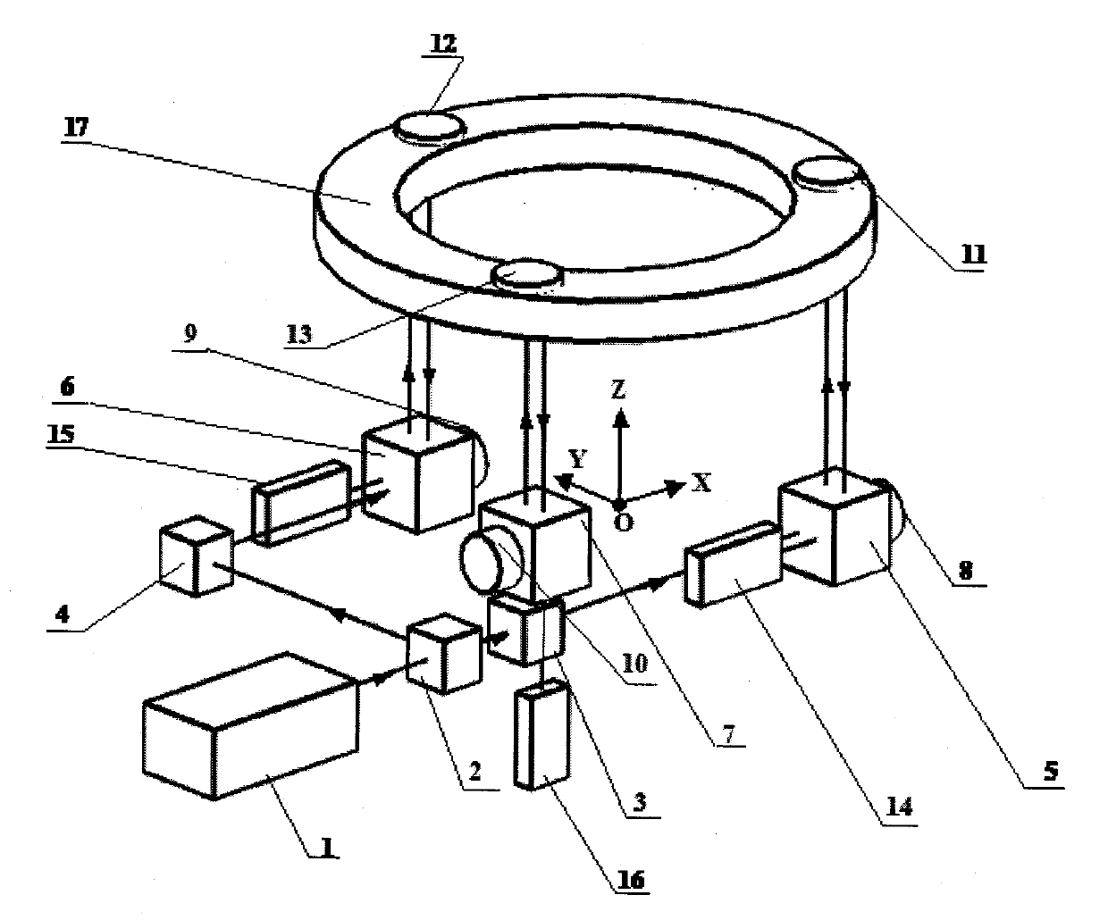
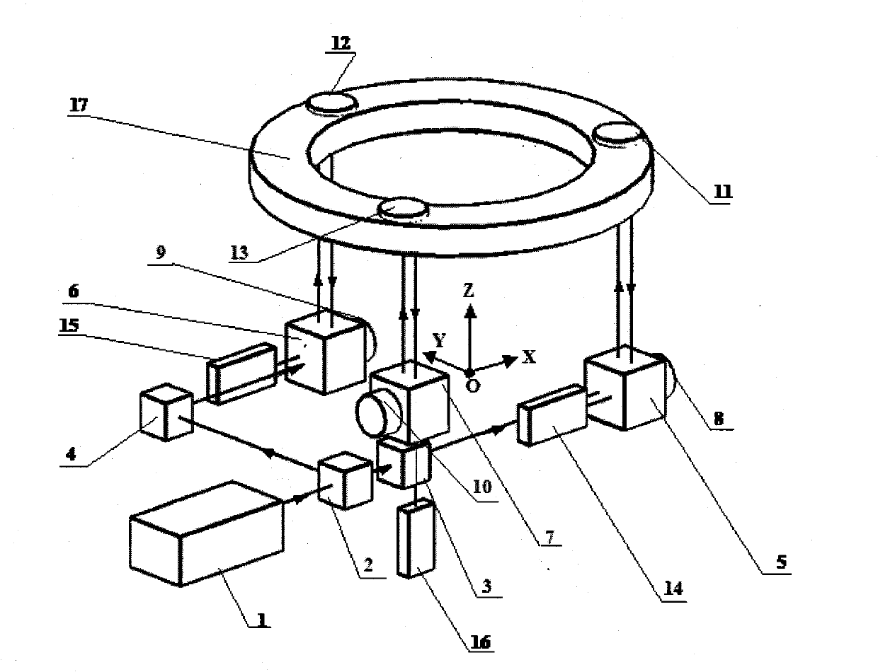
[0020] A displacement measurement device for a movable mutual induction coil of an energy balance, comprising a longitudinal Zeeman dual-frequency laser head 1, the dual-frequency laser head 1 has a built-in 1 / 4 wave plate, and outputs orthogonal linearly polarized light whose vibration directions are perpendicular to each other. The reference optical signal is output simultaneously in the laser head 1 of two frequencies, and a 30% first beam splitter 2 is arranged in the laser beam output direction of the longitudinal Zeeman dual-frequency laser head 1, and the laser beam output by the laser head 1 is divided into a reflected beam and a transmitted beam. Beam, the power ratio is 1: 2; The transmitted beam through the first beam splitter 2 is along the beam direction output by the laser head, and the transmitted beam direction of the first beam splitter 2 is equipped wi...


PUM


Abstract

The invention relates to a displacement measuring device for a movable mutual inductor of an energy balance. The device comprises a double-frequency laser head, wherein a first beam splitter is arranged in the laser beam output direction of the double-frequency laser head; a beam deflector is arranged in the reflected beam direction of the first beam splitter; a second beam splitter is arranged in the transmitted beam direction of the first beam splitter; a polarized beam-splitting prism is arranged in the transmitted and reflected beam directions of the second beam splitter; a corner cube prism is arranged in the transmitted and reflected beam directions of the polarized beam-splitting prism; a light receiver is arranged in the reflected and transmitted beam converging direction of the polarized beam-splitting prism; a laser beam output by the double-frequency laser head is divided into a transmitted beam, a reflected and steered translational beam and a reflected beam having equal light energy through the beam splitter and the beam deflector having different energy transmittances, and the three beams are orthogonal polarized light vertical to a beam transmission direction; and the displacement of the center of mass of the movable mutual inductor is obtained through the displacements of three heterodyne interference measuring light paths. The device has the characteristics of multichannel multiplexing and small signal noise.

Description

technical field [0001] The invention belongs to the technical field of laser precision measurement, in particular to a displacement measuring device for a movable mutual induction coil of an energy balance. Background technique [0002] The coil system of the energy balance device includes a fixed mutual induction coil and a movable mutual induction coil. The fixed mutual induction coil is installed on a stable vibration isolation platform to generate a uniform radial magnetic field. The movable mutual induction coil is ring-shaped, connected by three support rods and hung on one end of the balance beam through a hook. The inner and outer diameters are 200mm and 280mm respectively. The electromagnetic force balanced by the standard weight at the other end of the beam. [0003] The movable mutual induction coil moves up and down within a 20mm travel range in the vertical direction, requiring precise positioning of the centroid of the coil at several different positions to a...

Claims


Application Information

Patent Timeline
Patent Type & Authority Applications(China)
IPC IPC(8): G01B11/02
Inventor 张丽琼李岩刘振张继涛
Owner TSINGHUA UNIV
Why Eureka
Try Eureka